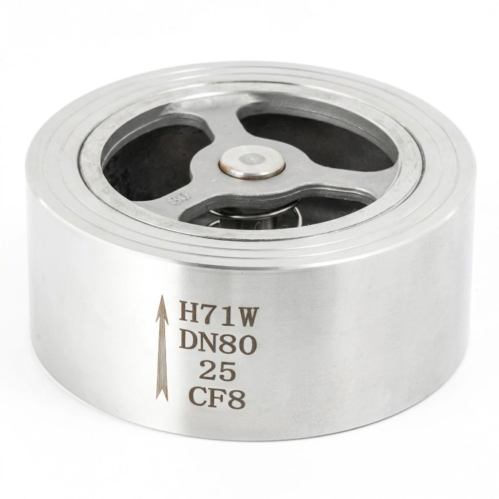
H71H / H71W Wafer Lift Check Valve
• PN16/PN25/PN40 wafer lift check valve, DN15–DN150, ≤425°C
• Ultra-compact wafer design installs between two pipe flanges
• Three material grades: 2Cr13, 1Cr18Ni9Ti (304), 1Cr18Ni12Mo2Ti (316)
• Suitable for water, steam, oil, nitric acid, acetic acid
• Can be installed on both vertical and horizontal pipelines
Contact Us for Pricing
Interested in this product? Contact us now for detailed pricing and product information.
Product Details
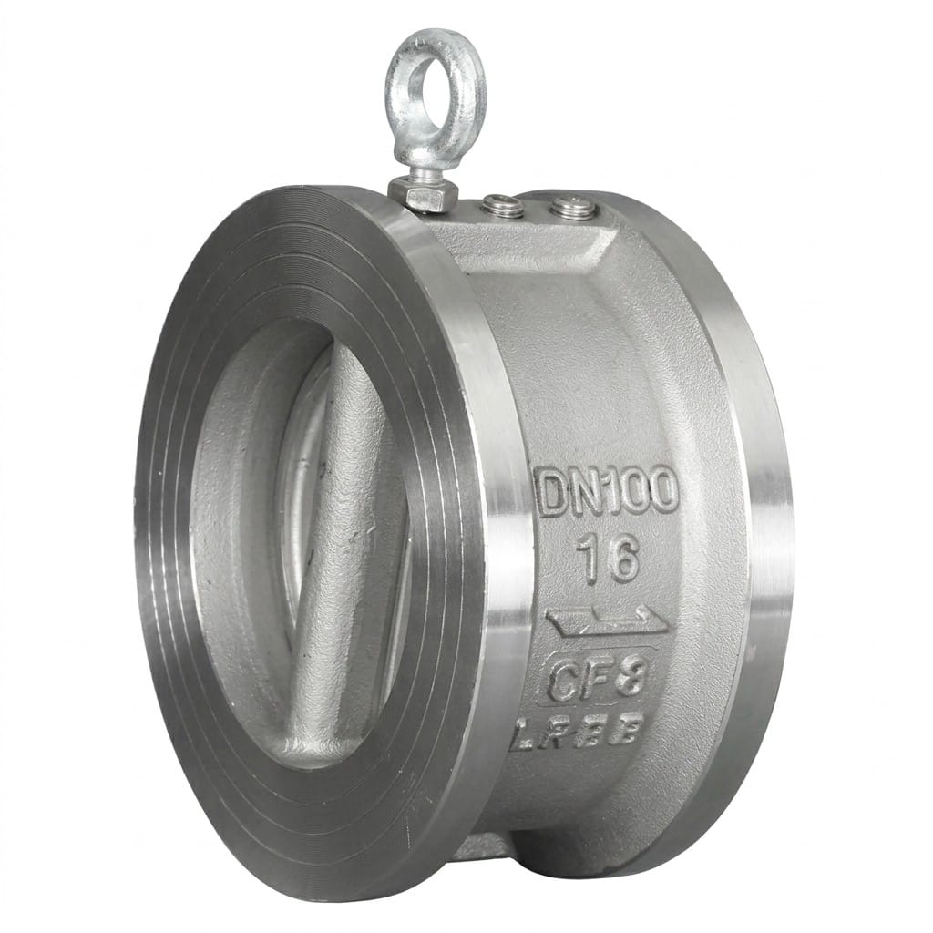
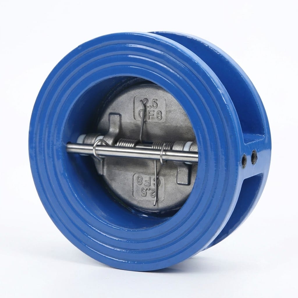
The H71H and H71W wafer lift check valves stop backflow in the thinnest possible section: the valve is clamped directly between two standard pipe flanges using the line’s own bolt set, with a face-to-face as short as 16 mm at DN15. A lightweight guided disc lifts on forward flow and drops shut on its own weight when flow stops or reverses, giving the rapid, low-inertia closure that protects a pump and its piping from water hammer. PN16, PN25 and PN40 classes cover DN15 to DN150 at up to 425°C, in three material grades — 2Cr13, 1Cr18Ni9Ti (AISI 304) and 1Cr18Ni12Mo2Ti (AISI 316) — on horizontal or vertical lines.
- Wafer (between-flanges) body — installs with the pipeline’s own bolts, L from 16 mm, saving space over flanged check valves
- PN16, PN25 and PN40 classes across DN15–DN150, working to 425°C
- Three material grades: 2Cr13 for water, steam and oil; 1Cr18Ni9Ti (304) for nitric acid; 1Cr18Ni12Mo2Ti (316) for acetic acid and severe corrosion
- Lightweight guided disc closes fast with low water-hammer spike — built for pump discharge protection
- Installs on horizontal or vertical lines (upward flow) without modification
- All-metal construction with no springs, bearings or actuators — near-zero maintenance overhead
Product Overview
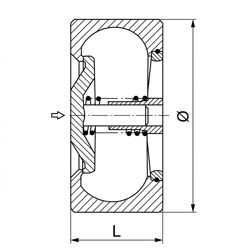
The H71H / H71W is an ultra-slim non-return valve that sits between two pipe flanges and is held by their studs. There is no integral flange to bolt to, no separate mounting hardware and almost no added line length, which is why this pattern is the default in pump rooms, skids, heat-exchanger branches and plant retrofits where the space between flanges is already spent. The disc lifts vertically on precision guides: forward flow pressure opens it against gravity alone, and when flow stops or reverses the disc falls back onto its seat under its own weight. One shorthand note: “no additional bolts” means the pipeline’s own studs hold the valve — a gasket on each side is still required.
Selection is by grade and class first. The 2Cr13 grade (H71H) covers water, steam, oil and petroleum to 425°C; 1Cr18Ni9Ti (H71W-16P and friends) is the nitric acid grade; 1Cr18Ni12Mo2Ti (H71W-16R) adds molybdenum for acetic acid and more severe corrosive media. PN16, PN25 and PN40 share the same compact L dimensions in the table below, so the class is a rating decision, not a space decision.
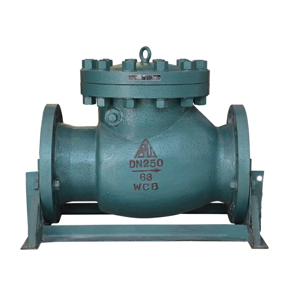
And when not to use it: a wafer valve cannot carry pipe weight and its sealing depends on two parallel, evenly-clamped flange faces — if the line relies on the valve for rigidity, if the mating faces are old or uneven, or if you need DN above 150, go back to a flanged pattern such as the H41H lift check valve or the H44H swing check valve. Where the line is large, wafer diameter is the constraint and the H76H/H double disc wafer check covers bigger bores in a shorter section than any flanged valve.
What the Model Code Means
H = check valve, 7 = wafer / between-flanges connection, 1 = lift (guided disc) pattern; the fourth letter gives the material — H marks the 2Cr13 general-service grade (H71H) and W the stainless grades (H71W). The digits give the class and the body suffix follows the page’s own model table: -16C for the carbon-steel 2Cr13 line, -16P / -25P for 1Cr18Ni9Ti (304) and -16R / -25R for 1Cr18Ni12Mo2Ti (316). See the Valve Model Decoder for the full system.
Core Strengths
Ultra-Compact Wafer Design
Extremely slim profile designed to fit between standard flanges without additional gaskets or bolts. Saves significant pipeline space compared to flanged check valves—ideal for space-constrained installations.
Rapid Closure & Low Water Hammer
Lightweight disc closes quickly when flow stops, minimizing water hammer pressure spikes in pump discharge lines. The low-inertia design ensures fast response while maintaining smooth operation.
Minimal Flow Resistance
Streamlined internal flow path with low-pressure drop characteristics. The wafer body profile reduces turbulence and energy loss, improving overall system efficiency in continuous-flow applications.
Dual Installation Flexibility
Can be installed on both vertical pipelines and horizontal pipelines without modification. The guided disc mechanism functions reliably in either orientation—simplifies system design and inventory management.
Triple Material Options for Corrosion Service
Available in 2Cr13 carbon steel (water, steam, oil), 1Cr18Ni9Ti austenitic stainless steel (nitric acid), and 1Cr18Ni12Mo2Ti molybdenum stainless steel (severe corrosive media including acetic acid).
Simple Structure & Easy Maintenance
All-metal construction with minimal moving parts. No springs, bearings, or external actuators required—the self-guiding disc mechanism delivers reliable performance with near-zero maintenance overhead.
Performance Specifications
| Parameter | PN16 | PN25 | PN40 |
|---|---|---|---|
| Model (Carbon Steel) | H71H-16C | H71H-25 | H71H-40 |
| Model (Stainless 304) | H71W-16P | H71W-25P | H71W-40P |
| Model (Stainless 316) | H71W-16R | H71W-25R | H71W-40R |
| Nominal Pressure (MPa) | 1.6 | 2.5 | 4.0 |
| Shell Test Pressure (MPa) | 2.4 | 3.8 | 6.0 |
| Seal Test Pressure (MPa) | 1.8 | 2.8 | 4.4 |
| Max. Working Temperature | ≤425°C | ≤425°C | ≤425°C |
| Body Material | 2Cr13 / 1Cr18Ni9Ti / 1Cr18Ni12Mo2Ti Stainless Steel | 2Cr13 / 1Cr18Ni9Ti / 1Cr18Ni12Mo2Ti Stainless Steel | 2Cr13 / 1Cr18Ni9Ti / 1Cr18Ni12Mo2Ti Stainless Steel |
The 425°C figure is the metal-seated limit for the 2Cr13 grade; confirm the grade-specific ceiling for the stainless options against your medium rather than the nameplate. Shell and seat pressures are hydraulic proof values per class.
Material Selection Guide
| Material Grade | Valve Body | Disc | Best Suited For |
|---|---|---|---|
| 2Cr13 (Carbon Steel) | 2Cr13 | 2Cr13 | Water, Steam, Oil, Petroleum |
| 1Cr18Ni9Ti (AISI 304) | 1Cr18Ni9Ti | 1Cr18Ni9Ti | Nitric Acid Environments |
| 1Cr18Ni12Mo2Ti (AISI 316) | 1Cr18Ni12Mo2Ti | 1Cr18Ni12Mo2Ti | Nitric Acid, Acetic Acid, Severe Corrosive Media |
Match the grade to the medium, not the price. Nitric acid points to 1Cr18Ni9Ti, acetic acid and mixed corrosive service point to 1Cr18Ni12Mo2Ti, and everything that is simply water, steam or oil runs on 2Cr13. Give us the concentration and temperature of any acid line.
Main Dimensions & Weights
Dimensions PN10 / PN16
| Nominal size | L (mm) | D (mm) | Weight (kg) |
|---|---|---|---|
| DN15 | 16 | 53 | 0.3 |
| DN20 | 19 | 63 | 0.5 |
| DN25 | 22 | 73 | 0.7 |
| DN32 | 28 | 84 | 1.2 |
| DN40 | 32 | 94 | 1.5 |
| DN50 | 40 | 109 | 2.2 |
| DN65 | 46 | 129 | 3.1 |
| DN80 | 50 | 144 | 4.0 |
| DN100 | 60 | 164 | 5.2 |
| DN125 | 90 | 194 | 8.6 |
| DN150 | 106 | 220 | 11.6 |
Dimensions PN25
| Nominal size | L (mm) | D (mm) | Weight (kg) |
|---|---|---|---|
| DN15 | 16 | 53 | 0.3 |
| DN20 | 19 | 63 | 0.5 |
| DN25 | 22 | 73 | 0.7 |
| DN32 | 28 | 84 | 1.2 |
| DN40 | 32 | 94 | 1.5 |
| DN50 | 40 | 109 | 2.2 |
| DN65 | 46 | 129 | 3.1 |
| DN80 | 50 | 144 | 4.0 |
| DN100 | 60 | 170 | 5.2 |
| DN125 | 90 | 198 | 8.6 |
| DN150 | 106 | 228 | 11.6 |
Dimensions PN40
| Nominal size | L (mm) | D (mm) | Weight (kg) |
|---|---|---|---|
| DN15 | 16 | 53 | 0.3 |
| DN20 | 19 | 63 | 0.5 |
| DN25 | 22 | 73 | 0.8 |
| DN32 | 28 | 84 | 1.3 |
| DN40 | 32 | 94 | 1.8 |
| DN50 | 40 | 109 | 2.6 |
| DN65 | 46 | 129 | 3.6 |
| DN80 | 50 | 144 | 4.8 |
| DN100 | 60 | 170 | 5.9 |
| DN125 | 90 | 198 | 9.8 |
| DN150 | 106 | 228 | 13.6 |
L = face-to-face length, D = outer diameter of the wafer body, weight in kg; values as published for reference. Note the identical L at every class and the D stepping up at DN100 and above — the wafer diameter, not the length, is what a tight installation runs into. Certified drawings are issued with the quotation.
Wafer or Flanged: Which Check Valve Body to Specify
| Requirement | H71H / H71W wafer lift check | H41H flanged lift check |
|---|---|---|
| Space in the line | Minimal — 16–106 mm between existing flanges, no extra bolting | Integral flanges add face-to-face length and a full joint either side |
| How it is held | Clamped by the pipe flanges’ own bolt set, gasket each side | Bolted to mating flanges as a line component |
| Pipe loads | Must not carry pipe weight; flanges must do the supporting | Rigid line member — but still needs support, per good practice |
| Flange faces | Needs two parallel, evenly-tightened faces; star-pattern torque or the thin body distorts | Conventional flange joint, less sensitive to stud tightening sequence |
| Pressure classes on this page | PN16 / PN25 / PN40 | PN16 / PN25 |
| Sizes | DN15–DN150 | DN25–DN200 |
| Temperature | to 425°C, all classes | 200 / 300 / 425°C by body material |
| Choose it when | Space or weight dominates and the flanges are true | Larger bores, ageing flanges, or the line needs valve rigidity |
The trade in one sentence: with a wafer you buy centimetres and kilograms, and you pay for them with total dependence on the pipeline’s flange faces. A new pump-discharge spool suits the wafer’s short closure and low inertia; an old header with distorted faces is better served by a flanged pattern that brings its own joint geometry. Both are gravity-closing lift discs — the body style, not the mechanism, is what you are choosing between.
Structure Drawing
Design & Manufacturing Standards
- Design Standard: GB/T 12236
- Face-to-Face Dimensions: GB/T 12221
- Flange Standards: GB/T 9113, JB/T 79, HG/T 20592
- Testing & Inspection: GB/T 13927, JB/T 9092
- Applicable International Standards: EN 13709, EN 558, API 594 (optional)
The flange standards listed matter more on a wafer than on any other valve, because the body seals directly against your flanges. Tell us the facing type and standard of the mating flanges with the enquiry; API 594 is available as an optional reference.
Installation & Maintenance Guidelines
- Wafer Mounting: Install the valve between two flanges using the same bolt set. Ensure proper alignment of the valve bore with the pipeline centerline. Use appropriate gaskets on each side of the valve body for reliable sealing.
- Flow Direction: Install the valve with the correct orientation as indicated by the flow direction arrow marked on the valve body. Reverse flow direction will cause the valve to malfunction.
- Flexible Orientation: This valve can be installed on both vertical and horizontal pipelines without affecting performance. For vertical installations, ensure medium flows upward for optimal disc action.
- Bolt Torque Sequence: Tighten flange bolts gradually in a star pattern to avoid uneven compression on the wafer body. Over-tightening can distort the thin-profile body and affect disc movement.
- Maintenance: Periodically inspect the guided disc and seat surface for wear or corrosion. Clean the guide passages to ensure free disc travel. Replace the valve if excessive scoring or deformation is observed on sealing surfaces.
Application Fields
The fields are water supply systems, steam distribution networks, chemical processing plants, petroleum refineries, hvac & heating systems, pharmaceutical industry, food & beverage processing, marine applications. In practice the split follows the material grade: 2Cr13 valves go into water supply, steam distribution, HVAC heating circuits and refinery water/oil services; the 304 grade answers nitric acid handling in chemical plants; the 316 grade covers acetic and mixed corrosive duty in pharmaceutical and food or beverage piping, and marine systems where space between flanges is always short.
What We Need to Quote Your H71H / H71W Valves
- Size and quantity: DN15–DN150, mixed lists welcome.
- Pressure class: PN16, PN25 or PN40 per the ratings table.
- Medium and concentration: drives the grade — 2Cr13, 304 or 316.
- Temperature: up to 425°C on the 2Cr13 grade; confirm for stainless.
- Mating flanges: standard and facing type (GB/T 9113, JB/T 79, HG/T 20592, or state yours).
- Orientation: horizontal, or vertical with upward flow.
- Documentation: EN 10204 3.1 certificates and test records for tenders.
A valve schedule with DN, class, medium and flange standard is enough to price the list and confirm wafer diameter against your flanges. Drawings are in the download center and qualifications on the certifications page.
Frequently Asked Questions
What is the difference between H71H and H71W?
The body and disc material. H71H is the 2Cr13 grade for water, steam, oil and petroleum up to 425 degC. H71W is the stainless family: 1Cr18Ni9Ti (AISI 304) for nitric acid environments, and 1Cr18Ni12Mo2Ti (AISI 316) for acetic acid and more severe corrosive media. Dimensions, classes and the guided lift disc are the same across the series.
Can a wafer check valve really be installed on a vertical pipe?
Yes – this pattern is offered for both horizontal and vertical lines without modification, because the guided disc moves on its own axis regardless of orientation. On vertical runs the medium must flow upward, so gravity helps the disc close rather than fight it. That is a point of difference from the PN25 gas lift check valve in this range, which the pages here list for horizontal service only.
How do I install it between flanges without crushing the body?
Center the valve on the bore, use a gasket on each side suited to the medium, and tighten the flange studs gradually in a star pattern. The wafer body is thin: uneven or over-tight clamping distorts it and can bind the disc guide. Align the flanges before the valve goes in.
Will it fit my non-GB flanges?
Usually, but check two things: the facing type and the bolt circle. The wafer locates on the raised faces, so its outer diameter must sit inside them while still covering the pipe bore – compare against the D column in the dimensions table. Send the flange standard you use and we confirm fit before order.
Is a wafer lift check quiet on pump shutdown?
Quieter than a swing check of comparable size, because the low-inertia disc starts dropping the moment forward flow decelerates, which limits the hammer spike. If a large pump that trips hard is the duty and noise governs, a purpose-built non-slam design such as the H42F silent check valve is the better answer.
What pressure do these valves see in testing?
Hydraulic proof testing per class: PN16 shell 2.4 MPa and seat 1.8 MPa, PN25 shell 3.8 MPa and seat 2.8 MPa, PN40 shell 6.0 MPa and seat 4.4 MPa, to GB/T 13927 and JB/T 9092. Additional or witnessed testing can be arranged.
Gaoshan Valve has manufactured industrial valves since 1975 and holds ISO 9001/14001/45001 with CE, API 6D and PED product certification. It is an approved supplier to Sinopec, CNPC and State Grid and exports to more than 30 countries, supplying water utilities, power plants and EPC contractors.
Get a Quote & Technical Support
Contact Gaoshan Valve for dimension sheets, CAD drawings, material certifications and a grade recommendation matched to your medium. If the wafer section is the reason you are here, we will also tell you when it is the wrong choice. Reply within 24 hours from our overseas sales desk.