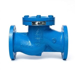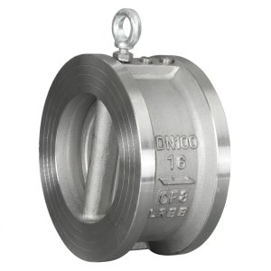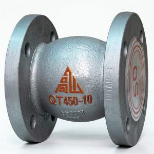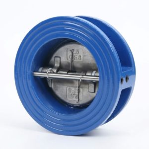
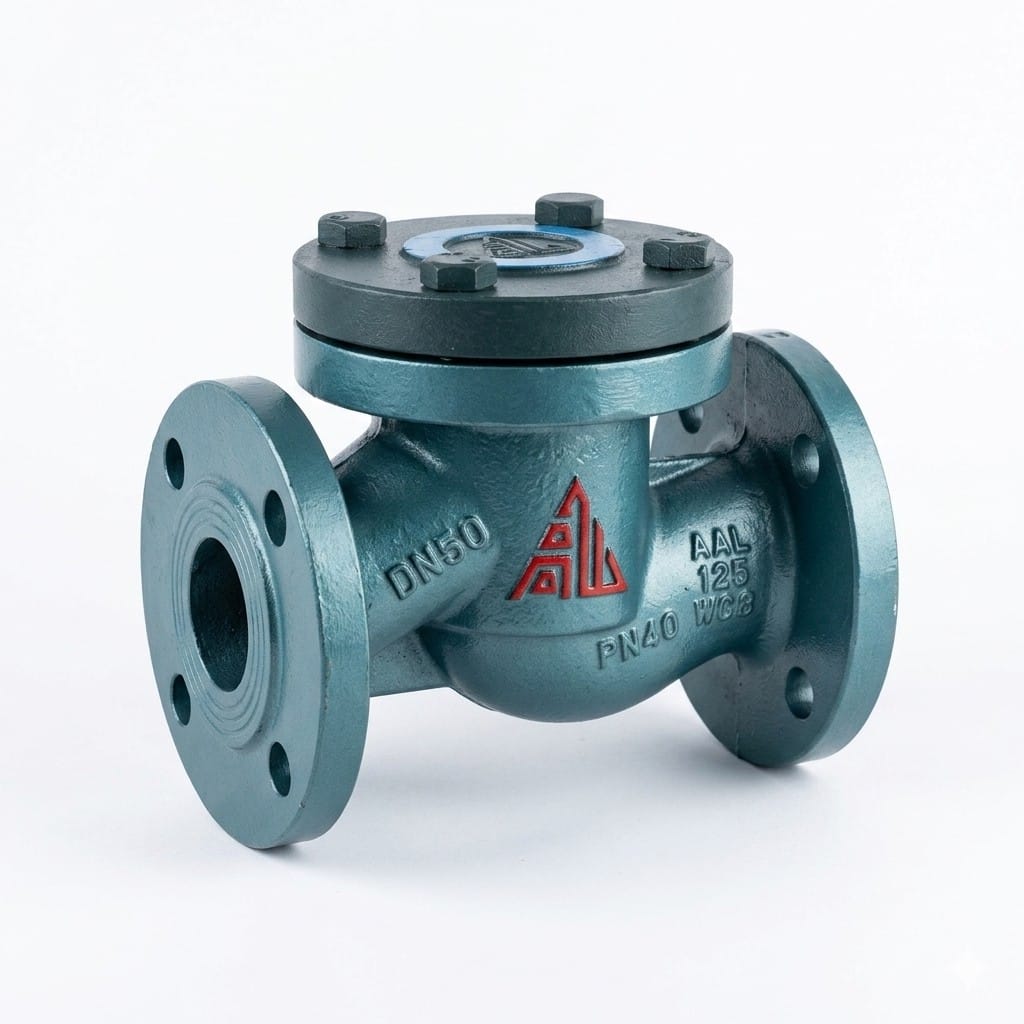
RH41F-25 Gas Lift Check Valve
- Product Model: RH41F-25 Gas Lift Check Valve
- Pressure Rating: PN25 (2.5MPa)
- Connection Type: Flanged connection
- Structure: Lift type with gravity-operated disc
- Body Material: WCB cast steel
- Sealing Material: 2Cr13 stainless steel disc/seat with 2Cr13/PTFE seal ring
- Applicable Media: Gas (natural gas, LPG), water, petroleum products
- Working Temperature: ≤100℃
- Core Function: Automatically prevents medium backflow using fluid pressure difference and disc gravity
- Application Scenarios: Gas pipeline systems, liquefied petroleum gas pipelines, water and oil delivery systems
Contact Us for Pricing
Interested in this product? Contact us now for detailed pricing and product information.
Product Details
The RH41F-25 gas lift check valve is a flanged, PN25 (2.5 MPa) non-return valve built for gas pipeline service — natural gas, liquefied petroleum gas and other fuel gas — where backflow after a compressor, blower or pump stop is unacceptable. A guided lift disc rises on forward flow and drops back onto its 2Cr13 stainless seat by gravity and reverse differential the moment flow reverses, so the valve needs no external power, control signal or operator. The WCB cast steel body, the 2Cr13 disc and seat and the 2Cr13/PTFE composite seal ring cover gas, water, oil and petroleum duty at temperatures up to 100°C, in ten sizes from DN25 to DN200.
- PN25 (2.5 MPa) gas-service lift check valve — shell test 3.8 MPa, seal test 2.8 MPa
- Purpose-designed for gas pipeline systems, LPG lines and water or oil delivery service
- WCB cast steel body and bonnet with 2Cr13 stainless steel disc and seat ring
- 2Cr13/PTFE composite seal ring for tight shut-off on gas media up to 100°C
- Automatic operation — disc opens and closes on fluid differential pressure and its own weight, no external power
- Flanged ends to GB/T 9113 / JB/T 79, flow direction marked on the body, DN25–DN200 with weights from 6 to 190 kg
Product Overview
The RH41F-25 is an automatic non-return valve for medium-pressure gas distribution and fuel-gas piping: compressor and blower discharge protection, gas metering stations, and the water or oil sections of mixed industrial services. It is a lift-pattern (globe-type) check valve — the disc travels on a guided path square onto the seat, which gives short, positive closure travel and a seat that is pressed closed by reverse pressure as well as by the disc’s own weight.
Gas is demanding for a check valve for a simple reason: a gas leak starts at a surface defect that a liquid would bridge. Density and viscosity are lower, so seat finish, disc guidance and body rigidity matter more than they do on water. That is what this design is built around — a machined 2Cr13 stainless disc and seat, a 2Cr13/PTFE composite seal ring as the secondary barrier, and a WCB cast steel body that holds flange alignment at PN25. The 100°C ceiling is set by the sealing materials; on gas, treat it as a hard limit, not a nameplate.
Equally, know when this is the wrong valve. Above 100°C or on steam, the H41H flanged lift check valve in the same family is the correct metal-seated selection. For a command function — open and close for maintenance or emergency — you need an isolation valve, the RQ41F gas ball valve; in practice most gas stations fit both, an RH41F for backflow and an RQ41F upstream for shutdown. And a check valve left part-open washes its own seat: it is an automatic device, not a regulator.
What the Model Code Means
RH41F-25: an H = check valve, 4 = flanged connection, 1 = lift (guided disc) pattern, F = fluoropolymer (PTFE) sealing element, matching the 2Cr13/PTFE composite seal ring in the materials table; 25 is the PN25 (2.5 MPa) pressure class. The leading R is the gas-service prefix used across this series on this site, as in RQ41F gas ball valves and RZ47F gas plate gate valves. Decode other codes on the Valve Model Decoder.
Core Strengths
Automatic Anti-Backflow
Disc opens and closes automatically by fluid differential pressure and gravity, effectively preventing medium backflow without external power or manual intervention.
Specialized for Gas Media
Purpose-designed for liquefied petroleum gas, natural gas, and other gas pipelines, with superior sealing performance and operational safety.
Durable Material Configuration
WCB cast steel body with 2Cr13 stainless steel disc and seat, plus 2Cr13/PTFE composite sealing ring for wear resistance and corrosion protection.
Simple & Reliable Structure
Lift-type design with minimal moving parts ensures stable long-term operation and easy maintenance with low lifecycle cost.
Wide Applicability
Suitable for gas, water, oil, and other media, covering a broad range of industrial pipeline applications with reliable performance.
Strict Pressure Testing
Designed and tested to PN25 (2.5 MPa) pressure standards with shell test at 3.8 MPa and seal test at 2.8 MPa for safe high-pressure operation.
Performance Specifications
| Model | Nominal Pressure (MPa) | Shell Test (MPa) | Seal Test (MPa) | Working Temp. (°C) | Applicable Medium |
|---|---|---|---|---|---|
| RH41F-25 | 2.5 | 3.8 | 2.8 | ≤100 | Gas, Water, Oil, Petroleum |
One model, one class: PN25. The 3.8 MPa shell and 2.8 MPa seal figures are factory hydraulic proof tests; any additional gas-specific seat test your project requires should be stated in the enquiry. The 100°C limit and the tabulated media list should not be extended on assumed margin.
Main Component Materials
| Component | Material |
|---|---|
| Valve Body / Bonnet | WCB Cast Steel |
| Disc / Seat Ring | 2Cr13 Stainless Steel |
| Seal Ring | 2Cr13 / PTFE |
Three lines, deliberately: a cast steel pressure envelope, a stainless disc and seat for the gas sealing pair, and the 2Cr13/PTFE composite ring as the secondary seal. Bonnet bolting, gaskets and packing are confirmed on the quotation for your medium and temperature.
Main Dimensions & Weights (PN25)
| DN (mm) | Face-to-Face L (mm) | Height H (mm) | Handwheel Dia. D0 (mm) | Weight (kg) |
|---|---|---|---|---|
| 25 | 160 | 90 | 100 | 6 |
| 32 | 180 | 110 | 115 | 9 |
| 40 | 200 | 115 | 135 | 11 |
| 50 | 230 | 126 | 150 | 14 |
| 65 | 290 | 165 | 180 | 25 |
| 80 | 310 | 165 | 180 | 32 |
| 100 | 350 | 180 | 205 | 45 |
| 125 | 400 | 222 | 270 | 65 |
| 150 | 480 | 255 | 330 | 99 |
| 200 | 600 | 312 | 405 | 190 |
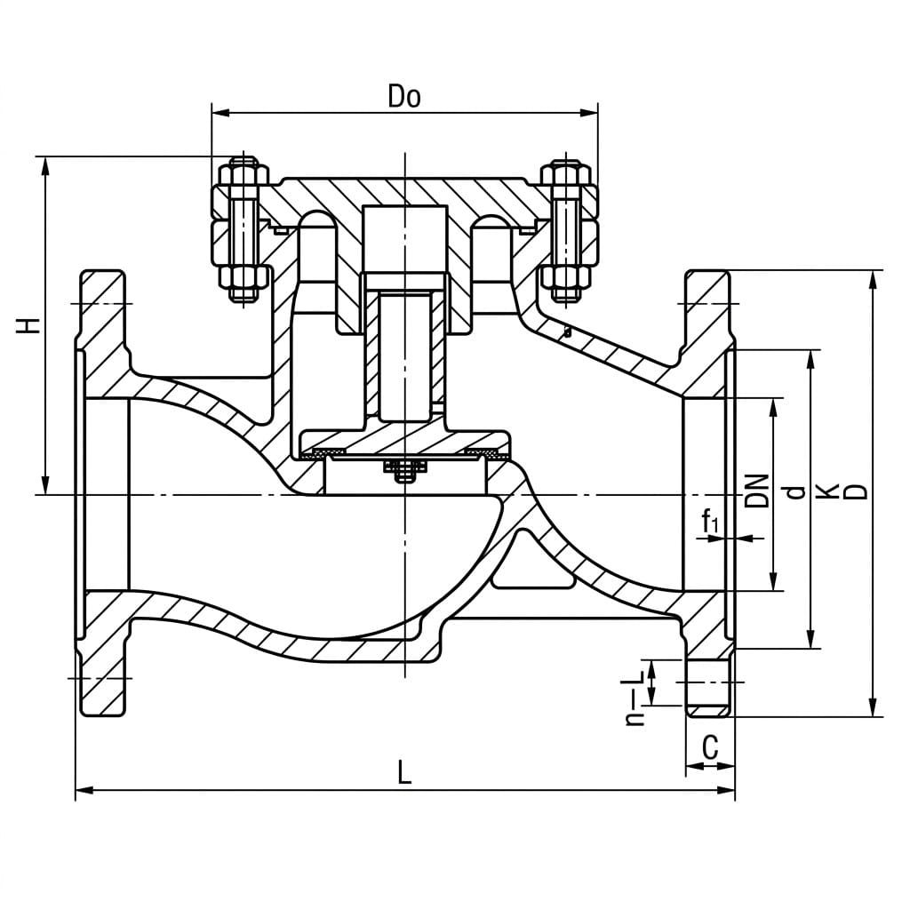
L = face-to-face length, H = overall height with the valve closed, D0 = handwheel diameter, weight in kg. Dimensions are for reference — certified drawings are issued with the quotation and in the download center. Large-diameter valves must be independently supported and must never carry pipeline weight; that applies across the range and especially at DN150 and DN200.
Which Valve for a Gas Line: RH41F vs H41H vs RQ41F
| Point of comparison | RH41F-25 gas lift check | H41H flanged lift check | RQ41F gas ball valve |
|---|---|---|---|
| Function in the line | Automatic backflow prevention only | Automatic backflow prevention only | Manual isolation — opens and closes on command |
| Rated on this page | PN25 (2.5 MPa) | PN16 and PN25 | PN16, PN25, PN40 |
| Sizes | DN25–DN200 | DN25–DN200 | DN15–DN300 |
| Temperature limit | ≤100°C | 200 / 300 / 425°C by body material | ≤100°C |
| Seat | 2Cr13 disc and seat + 2Cr13/PTFE composite seal ring | 2Cr13 stainless metal seat | Reinforced PTFE, hydrocarbon-compatible formula |
| Media per page | Gas (natural gas, LPG), water, oil, petroleum | Water, steam, oil, weakly corrosive media | Gas, water, petroleum |
| Installation | Horizontal pipe only — the disc closes on its own weight | Horizontal or vertical with upward flow | Per drawing |
| Gas safety features | Fire-safe and anti-static features are engineered to the standard your specification cites — send us the clause and we will confirm compliance | Not a gas-service listing | Anti-static grounding path and fire-safe design listed on its page |
Read the last row carefully before mixing the three up on a datasheet. The RH41F is the automatic backflow device — a hard stainless seat plus a PTFE composite ring sized for gas at up to 100°C. The RQ41F is the shut-off operated by hand for maintenance and emergency, and it is that page which lists anti-static and fire-safe design features. If your gas authority or plant standard requires fire-safe testing or anti-static devices on the check valve itself, say so in the enquiry: this page claims neither, and we will confirm what can be supplied rather than guess. Keep the line bonded and pipe-supported per plant standard, and let the valve do its two jobs — open on forward flow, close on reverse.
Structure Drawing
Design & Manufacturing Standards
- Design Standard: GB/T 12235
- Face-to-Face Dimensions: GB/T 12221
- Flange Standards: GB/T 9113, JB/T 79
- Testing & Inspection: GB/T 13927, JB/T 9092
- Applicable International Standards: EN 13709, EN 558 (optional)
These are the design and test standards the valve is built and proved to. Gas-industry certifications, fire-safe test reports or anti-static compliance are not listed on this page; send the applicable code or utility specification with your enquiry and we will confirm what can be documented.
Installation & Maintenance Guidelines
- Installation Requirements: Do not let the check valve bear pipeline weight; large-diameter valves require independent support to avoid excessive pipeline stress.
- Flow Direction: Install the valve with the medium flow direction matching the arrow marked on the valve body.
- Pipeline Orientation: Lift-type check valves must be installed on horizontal pipelines to ensure the disc moves freely under its own weight.
- Routine Maintenance: Regularly inspect the valve body, sealing surfaces, and disc for wear or damage to ensure reliable anti-backflow performance. Keep the pipeline free of debris to prevent disc jamming.
- Leak-test before gas: prove the flange joints by the plant’s pressure or leak-test procedure before the line is put into gas service; joints and gaskets, not the valve body, are the usual leak path.
- Gaskets for the medium: use gasket material compatible with the gas and with the 100°C limit, and replace rather than reuse crushed gaskets at reassembly.
- Bonding and support: where the system design calls for electrical continuity across the line, verify it after fitting the valve, and support the pipe either side so the valve never carries pipe weight.
Application Fields
The RH41F-25 is listed for gas transmission, lng/lpg systems, petroleum, chemical industry, pipeline systems, water supply — in practice: compressor and blower discharge on gas transmission and LPG systems, city-gas and plant fuel-gas lines, petroleum and chemical service within the tabulated media, and water supply lines on the same PN25 flanged class. Where the duty leaves the media list or exceeds 100°C, move to the H41H or a purpose-built pattern rather than adapting this one.
What We Need to Quote Your RH41F-25 Valves
- Size and quantity: DN25 to DN200, mixed lists welcome.
- Medium: natural gas, LPG or another gas, or water/oil duty — gas composition if known.
- Operating pressure and temperature: within PN25 and 100°C as tabulated.
- Pipe orientation: horizontal run, confirm flow direction against the body arrow.
- Flange standard: GB/T 9113 / JB/T 79 as listed; EN or ASME facing on request.
- Test and certificate requirements: any gas-code, fire-safe or anti-static requirement stated up front so we can confirm applicability.
- Documentation: EN 10204 3.1 certificates and test records for tender packages.
Send the line list or P&ID extract and we will confirm face-to-face, weight and seat arrangement for each size. Drawings are in the download center and qualifications on the certifications page.
Frequently Asked Questions
What makes a check valve suitable for gas rather than water service?
Gas starts to leak at surface defects a liquid would bridge, so the sealing pair matters: this valve uses a machined 2Cr13 stainless disc and seat with a 2Cr13/PTFE composite seal ring, in a WCB cast steel body that holds flange alignment at PN25. The 100 degC ceiling is set by the sealing materials. Fire-safe or anti-static requirements are not claimed on this page – give us the applicable code with the enquiry.
Can the RH41F-25 be installed on a vertical pipe?
No. The page states that lift-type check valves of this pattern must be installed on horizontal pipelines so the disc moves freely under its own weight, with the body arrow aligned to the flow direction. If your run is a vertical riser with upward flow, ask us about the vertical lift patterns in the check valve series instead.
What is the difference between the RH41F and the H41H?
Both are flanged lift-pattern check valves. The RH41F is the gas listing: PN25 only, capped at 100 degC, with the 2Cr13/PTFE composite seal ring. The H41H covers water, steam and oil at PN16 or PN25 with all-metal 2Cr13 seats rated to 200, 300 or 425 degC by body material. Use the H41H where heat is the problem; use the RH41F where the medium is gas.
Do I need both an RH41F and an RQ41F on a gas line?
Usually yes, because they do different jobs. The RQ41F gas ball valve is the isolation valve you operate for maintenance or shutdown; the RH41F sits where backflow after a machine stop would cause damage and operates automatically. Neither replaces the other, and the RQ41F is the page that lists anti-static and fire-safe design features.
How is each valve tested before shipment?
Hydraulic proof testing to the figures on this page: 3.8 MPa shell and 2.8 MPa seat for PN25, under GB/T 13927 and JB/T 9092. If your project adds a gas bubble-tight seat test or witnessed inspection, list it in the enquiry so it goes into the test plan and the price.
Why would a brand-new check valve leak on a gas line?
Almost always debris, not the valve. Commissioning leaves scale, slag and gasket cuttings in the line, and anything held on a seat shows up immediately as a gas leak. Flush the line; if the station is live, isolate and inspect the seat rather than raising pressure to force it closed.
Gaoshan Valve has manufactured industrial valves since 1975 and holds ISO 9001/14001/45001 with CE, API 6D and PED product certification. It is an approved supplier to Sinopec, CNPC and State Grid and exports to more than 30 countries, supplying water utilities, power plants and EPC contractors.
Get a Quote & Technical Support
Contact Gaoshan Valve for dimension sheets, CAD drawings and an honest answer on which gas-line standards your project can have documented. Reply within 24 hours from our overseas sales desk.