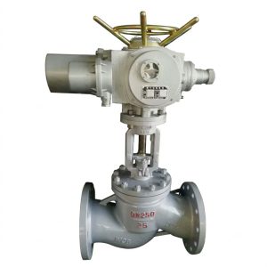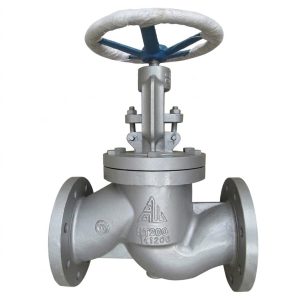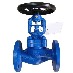
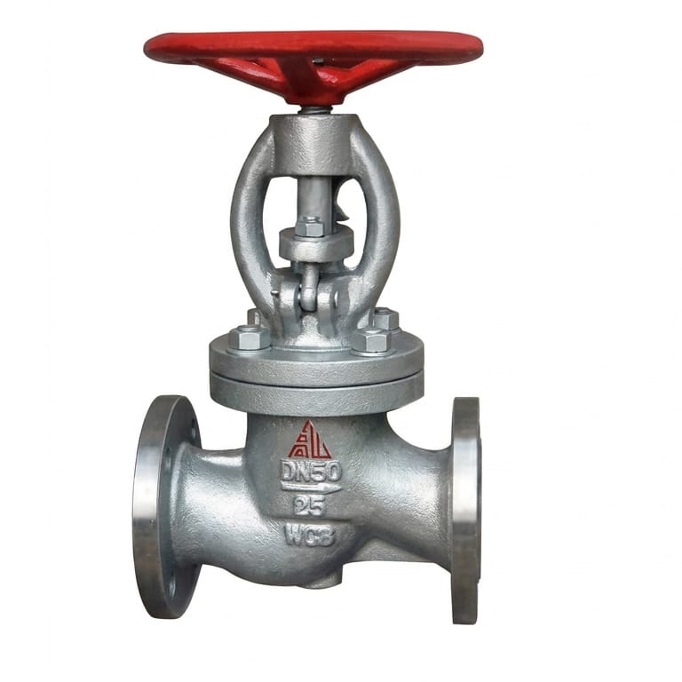
RJ41F Gas Globe Valve
The RJ41F Gas Globe Valve is engineered for reliable shut-off in gas distribution pipelines, petrochemical plants, and industrial systems. Designed for liquefied petroleum gas (LPG), natural gas, water, and oil products, it meets strict leak-prevention requirements.
- Pressure Rating: PN25 (2.5 MPa)
- Size Range: DN25 to DN200
- Temperature: Up to 100℃
- Reliable Sealing: Dual sealing with flexible graphite/PTFE packing and metal backup seal
- Materials: WCB carbon steel body with 2Cr13 stainless steel stem
- Safety Features: Anti-leakage, fire-safe design, self-compensating PTFE packing
Contact Us for Pricing
Interested in this product? Contact us now for detailed pricing and product information.
Product Details
The RJ41F-25 gas globe valve is a rising-stem, flanged shut-off valve built specifically for flammable gas service — LPG, natural gas and compressed fuel gas — where a stem or seat leak is a hazard, not just a loss. A 2Cr13 metal sealing face backed by a PTFE soft seal ring gives bubble-tight shut-off with a fire-safe metal contact behind it, and expanded graphite packing holds the seal when the temperature exceeds what PTFE alone can take. Rated PN25 for DN25 to DN200.
- Dual sealing: 2Cr13 metal-to-metal face backed by a PTFE soft seal ring for bubble-tight shut-off
- Fire-safe design intent for LPG, natural gas and other combustible media
- Rising stem with outside screw and yoke (OS&Y) gives unambiguous visual position indication
- Expanded graphite stem packing, self-compensating, stable across the full operating range
- WCB carbon steel body and bonnet with a 2Cr13 stainless steel stem
- PN25 (2.5 MPa), DN25–DN200, up to 100°C, flanged connection
Product Overview
The RJ41F-25 is a flanged globe valve purpose-built for gas service, covering liquefied petroleum gas, natural gas, compressed natural fuel gas and other combustible media where strict leak prevention and fire-safe behaviour are part of the specification rather than an option. It works at PN25 with a working temperature limit of 100°C, a ceiling set by the PTFE soft seal ring and the packing, and it is used as main line isolation, branch shut-off and emergency block in city gate stations, gas distribution networks, LPG storage and filling facilities and plant fuel gas systems.
A globe valve closes by pressing a disc squarely onto its seat, which is why it is preferred over a ball valve on gas duties where a positive, controlled closure and a robust metal backup seal matter more than speed. The trade is a longer, tortuous flow path and more turns of the handwheel — both acceptable, and usually preferred, on a gas line that is opened twice a year.
What the Model Code Means
RJ marks gas-service globe valve pattern, 4 = flanged connection, 1 = straight-through flow, F = PTFE soft seal; the -25 suffix is the PN25 pressure class. Check the coding against another supplier’s on our Valve Model Decoder.
Core Strengths
Dual Metal-and-PTFE Sealing
The disc carries a 2Cr13 stainless steel metal-to-metal sealing face backed by a PTFE soft seal ring. In normal service the soft seat does the work and the valve passes a low-pressure gas test bubble-tight; if the soft seat is ever damaged by heat or debris, the metal face remains as the backup barrier. That is what a fire-safe gas valve specification is asking for.
Fire-Safe Design for Combustible Gas
The body, bonnet and stem arrangement is designed to maintain containment when the soft seal is lost, which is the requirement behind fire-safe approval on LPG and fuel gas lines. Tell us the standard your specification cites and we will confirm the matching test documentation with the quotation.
Rising Stem with Outside Screw and Yoke
The stem rises with the disc, so the operator can see the valve is open from the yard without approaching the packing, and the yoke keeps the thread out of the gas path and clear of corrosion. On an isolation valve that protects a gas system, positive position indication is a safety function rather than a convenience.
Expanded Graphite Packing
Flexible graphite packing seals across the operating range and re-establishes stress as the plant cycles, which is why the valve is limited to 100°C by the PTFE soft seal rather than by the packing. The gland is adjustable in service, so a weeping stem can be corrected without a shutdown.
Stem Built for Wet Gas
The stem is 2Cr13 stainless steel rather than carbon steel, because natural gas and LPG leave a moisture film inside a distribution line that corrodes a plain stem and seizes it in the packing. The body and bonnet stay WCB carbon steel for strength and cost, with the corrosion resistance placed where it matters.
Low Operating Torque on a High Class Valve
The sealed seat geometry and the bearing arrangement keep handwheel effort reasonable at PN25, so DN150 and DN200 gates remain operable without a gear head. Send the differential pressure if your duty is at the top of the range.
Performance Specifications
| Model | Nominal Pressure PN (MPa) | Shell Test (MPa) | Seal Test (MPa) | Max Temp. (°C) | Applicable Medium |
|---|---|---|---|---|---|
| RJ41F-25 | 2.5 | 3.8 | 2.8 | ≤100 | Water, Gas, Petroleum Products, LPG, Natural Gas |
Shell test at 1.5x PN (3.8 MPa), seat test at 1.1x PN (2.8 MPa). The 100°C working limit protects the PTFE seal ring and keeps the graphite packing within its design margin; above that temperature the soft seat cold-flows and the bubble-tight seal is no longer guaranteed.
Materials of Main Parts
| NO | Part Name | Material |
|---|---|---|
| 1 | Valve Body, Bonnet | WCB Cast Steel |
| 2 | Valve Stem | 2Cr13 Stainless Steel |
| 3 | Packing | Expanded Graphite (Flexible) |
| 4 | Metal Seal Face | 2Cr13 Stainless Steel |
| 5 | Soft Seal Ring | PTFE (Polytetrafluoroethylene) |
| 6 | Handwheel | Ductile Cast Iron |
Main Dimensions & Weights
| DN (mm) | L | H | H 1 | D 0 | Weight (kg) |
|---|---|---|---|---|---|
| 25 | 160 | 285 | 300 | 160 | 7.4 |
| 32 | 180 | 302 | 327 | 180 | 8.5 |
| 40 | 200 | 355 | 385 | 200 | 12.5 |
| 50 | 230 | 362 | 397 | 240 | 16 |
| 65 | 290 | 365 | 405 | 280 | 25 |
| 80 | 310 | 369 | 420 | 280 | 30 |
| 100 | 350 | 370 | 425 | 320 | 34.5 |
| 125 | 400 | 558 | 608 | 400 | 89 |
| 150 | 480 | 611 | 692 | 400 | 98 |
| 200 | 600 | 721 | 806 | 400 | 170 |
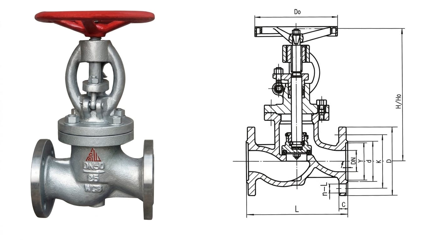
L = face-to-face length, H = handwheel centre height, H1 = open height, D0 = handwheel diameter; weights are nominal. Mating flange facing and drilling are confirmed at enquiry against your standard, and RF or RTJ faces are both available. Certified dimensional drawings are issued with the quotation.
Gas Globe Valve or Gas Ball Valve: Which to Specify
Both are sold for gas service and the choice is regularly made wrong, which is how a plant ends up with a leaking isolation point. Compare the two designs we build:
| Requirement | RJ41F gas globe valve | RQ41F gas ball valve |
|---|---|---|
| How it seals | Disc pressed squarely onto a seat; metal face behind the soft seal | Ball rotates onto two PTFE seats; quarter turn |
| Speed of operation | Several handwheel turns | 90 degrees, one movement |
| Position indication | Visible rising stem, unmistakable from a distance | Handle position only |
| Shut-off quality | Bubble-tight, with a metal backup for fire-safe duty | Bubble-tight on soft seats |
| Pressure drop | Higher – the flow path turns inside the body | Lower – bore is in line with the pipe |
| Best for | Main isolation, emergency block, infrequent operation | Frequently operated branch and distribution valves |
Rule of thumb: where the valve is an isolation or emergency block that is rarely cycled and where a visible, positively seated disc matters, specify the globe pattern. Where operators work the line often and pressure loss matters, specify the RQ41F gas ball valve.
Structure Drawing
Compliance, Testing and Documentation
- Every valve is shell tested at 3.8 MPa and seat tested at 2.8 MPa before packing, with records retained.
- Fire-safe design intent and the applicable gas pipeline safety requirements are confirmed on the quotation against the standard your specification cites.
- WCB body and bonnet material, 2Cr13 stem and seat face, and PTFE soft seal are documented on EN 10204 3.1 certificates for tender packages.
- RF or RTJ flange facings are available; tell us the mating flange standard so the drilling matches your spool.
- CE and API 6D documentation routes are available on request — see the certifications page.
Installation & Gas Service Safety
- Flow direction: fit the valve with the cast arrow matching flow direction — globe valves are directional and will not seal properly if reversed.
- Leak test after fitting: on gas service, always carry out a soap-bubble test at the stem packing after installation and before commissioning.
- Operate slowly: never snap the valve open or closed on a gas line; slow operation prevents pressure surge damage downstream.
- Grounding and bonding: bond the valve body to the piping so static discharge cannot become an ignition source in flammable gas service.
- Seat inspection: check the PTFE seal ring at planned shutdowns and replace it on any sign of cracking or deformation.
- Commissioning: purge and pressure-test the line to your own gas commissioning procedure before the valve is put into fuel gas service.
- Pipe support: support the pipe either side of a DN150 or DN200 valve so its weight and the bolt load are not carried by the body.
- Keep the indicator readable: the handwheel and rising stem must stay clear of insulation and standing water, and the position indication must be checked after the line is painted and lagged.
Application Fields
The RJ41F is deployed where combustible gas has to be isolated and the leak limit is not negotiable: City Gate Stations & Natural Gas Distribution Networks; LPG Storage Facilities & Bulk Transfer Terminals; CNG Compressor Stations & Vehicle Filling Infrastructure; Industrial Gas Utility Lines & Process Gas Shutoff Points; Petrochemical Plant Fuel Gas Systems; Emergency Block Valves on Combustible Gas Pipelines. In each of these the rising stem, the metal-backed seat and the adjustable graphite packing are what let an operator prove the isolation before work starts.
What We Need to Quote Your RJ41F Gas Valves
- Size and quantity: DN25–DN200.
- Gas and design pressure: LPG, natural gas or fuel gas, with the maximum operating pressure.
- Temperature range: PN25 with PTFE soft seal is limited to 100°C; above that we reassess the seat.
- Flange standard and facing: RF or RTJ, to your mating flange.
- Requirements list: fire-safe approval, anti-static provision, test medium and acceptance criteria.
- Accessories: lockable handwheel, chain wheel for high installations, position indicator or extension stem.
- Documentation: 3.1 certificates, test records and the gas pipeline code your project is inspected against.
Send the line list or the specification clause and we will confirm the class, seat arrangement and the paperwork your inspector will ask for. Drawings and catalogues are in the download center.
Frequently Asked Questions
Why is the RJ41F limited to 100 degC?
The soft seal ring is PTFE, which loses its preload and cold-flows as temperature rises, so the bubble-tight soft seal is guaranteed to 100 degC even though the metal face and graphite packing tolerate more. If your duty is hotter, tell us the design temperature and we will propose the correct seat arrangement.
Is this valve fire safe?
It is built to a fire-safe design intent: the 2Cr13 metal-to-metal sealing face remains as a backup barrier if the PTFE soft seal is destroyed by heat. Which approval your project requires – and against which standard – should be confirmed from your specification, and we will supply the matching test documentation with the quotation.
Why a globe valve instead of a ball valve on a gas line?
A globe valve closes by pressing a disc squarely onto its seat, giving a positive, controlled closure and a metal backup seal, and its rising stem shows the position from a distance. A ball valve is faster and has a lower pressure drop, so the RQ41F is preferred where the line is worked often. For main isolation and emergency block points the globe pattern is usually the specified answer.
Can it be installed on a horizontal pipe?
Yes, but gas globe valves are directional. Fit the valve with the cast arrow matching flow direction so the disc seats correctly and stem packing is not left under line pressure when the valve is open.
How do I prove the valve is closed before gas work starts?
The outside screw and yoke rising stem is the point of that design: the stem is visibly down when the valve is closed and rises when it opens. Confirm with the position of the stem, then carry out the soap-bubble or pressure-decay test your procedure requires at the packing and downstream flange.
Does the packing need a special tool to adjust?
No. The gland follower is adjusted at the nuts while the valve is cycled, in small increments only. If weeping continues after adjustment, the packing set is replaced at the next planned isolation rather than over-tightened, which would score the stem.
Get a Quote & Technical Support
Contact Gaoshan Valve for dimension drawings, seat and packing details, test records and a class recommendation for your LPG, natural gas or fuel gas isolation points. Reply within 24 hours from our overseas sales desk.