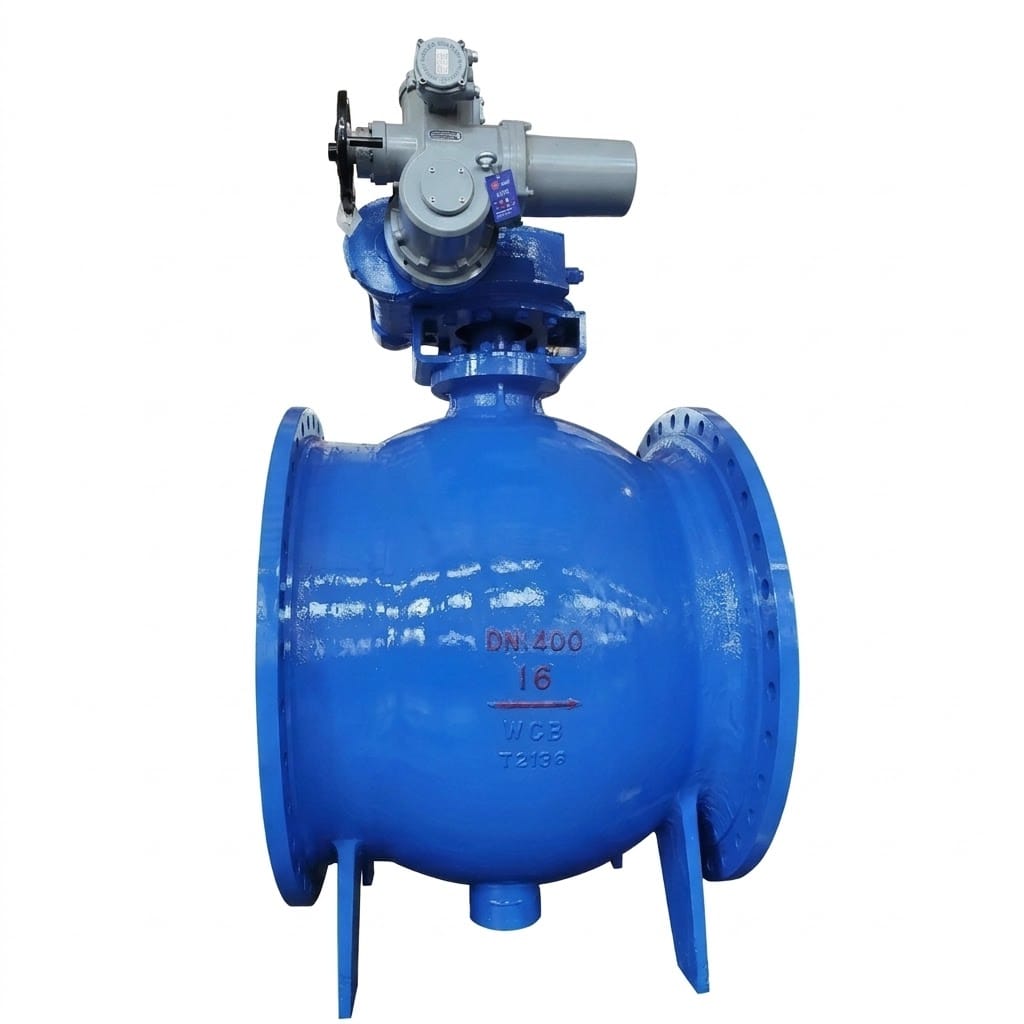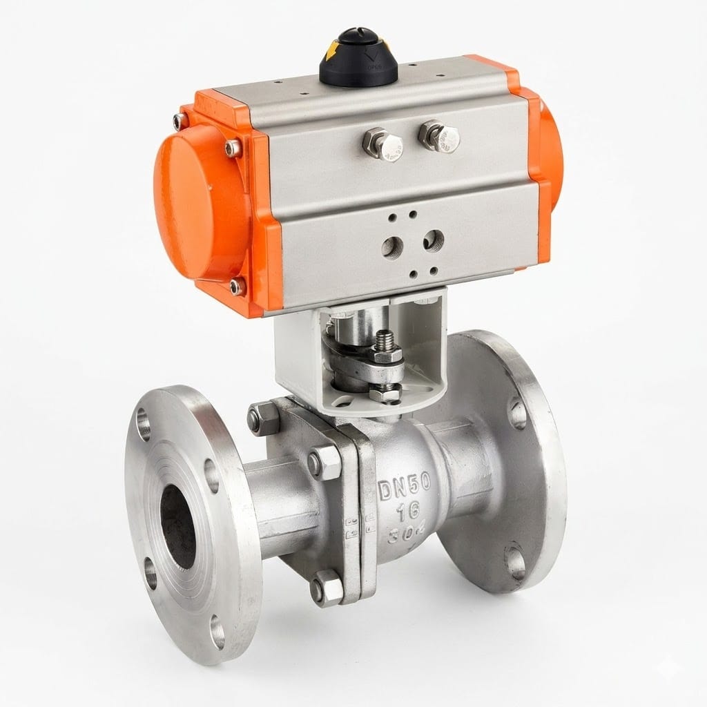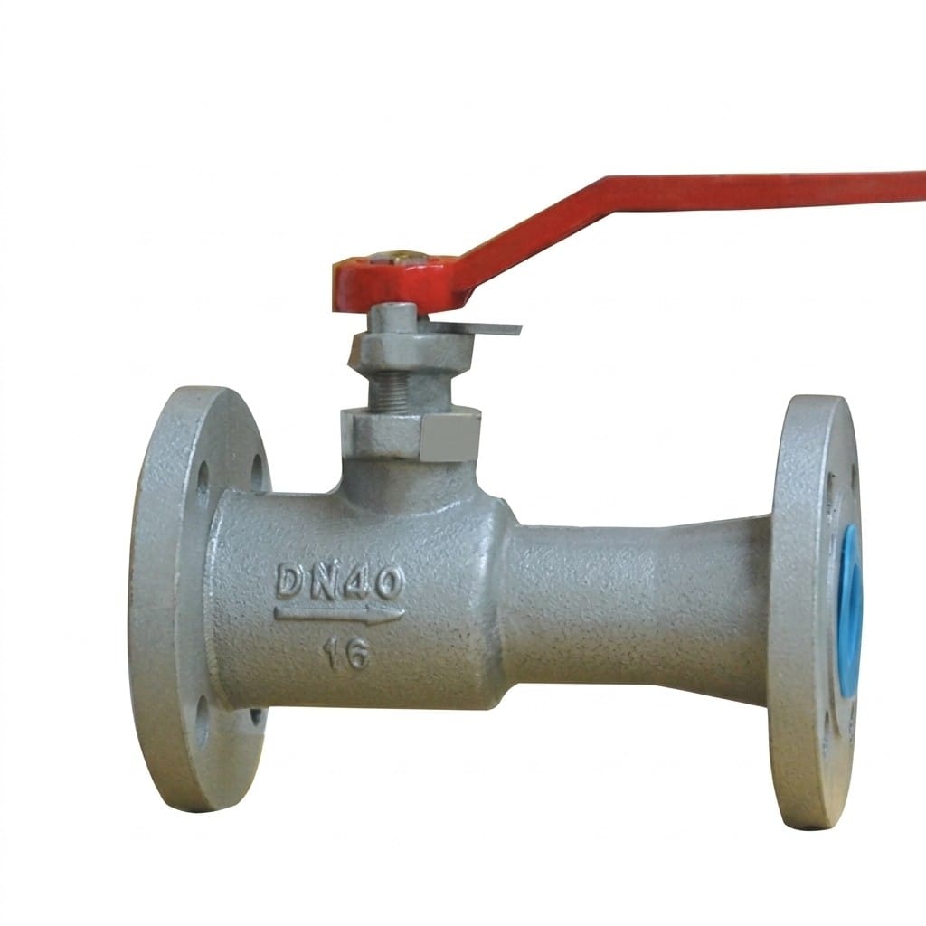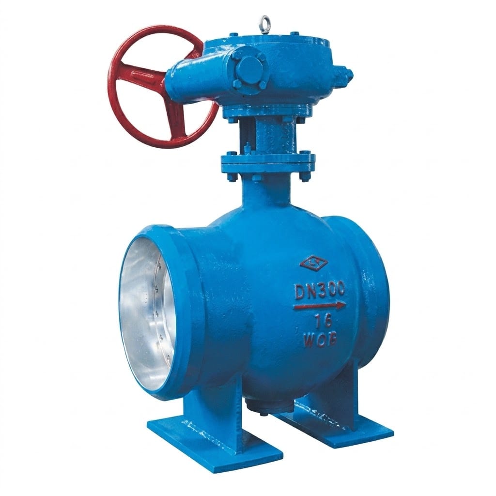
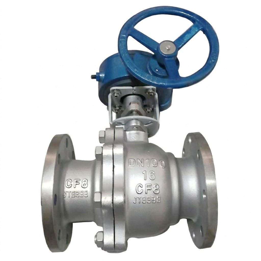
Q341F Worm Gear Operated Ball Valve
• Worm gear operated flanged ball valve for low-torque pipeline control
• Bi-directional sealing with PTFE/hard seat options (≤150℃ / ≤450℃)
• PN16/25/40 pressure ratings, DN15-DN300 full size range
• Fire-safe & anti-static design for industrial applications
• WCB/304/316 materials compatible with water, gas, oil and corrosive media
Contact Us for Pricing
Interested in this product? Contact us now for detailed pricing and product information.
Product Details
The Q341F worm gear operated ball valve puts a lever-action ball valve behind a self-locking gear head, so a DN150 or DN200 line can be opened and closed by hand without a torque multiplier and without the handle being wrenched by pressure surges. Built on the proven Q41F flanged ball valve platform, it keeps the full bore, floating ball and PTFE seats, and adds PN16 to PN40 classes across DN20 to DN200.
- Worm gear head with roughly 20:1 to 60:1 reduction, depending on size and class
- Self-locking gear train holds position against vibration and line pressure swings
- Full bore passage matches the pipe bore, so pressure loss across the open valve is minimal
- Anti-blowout stem with shoulder larger than the packing bore, plus PTFE or flexible graphite packing
- Five model variants: QT450-10 ductile iron (16Q/25Q) or WCB cast steel (16C/25/40)
- PN16, PN25 and PN40; DN20–DN200; up to 200°C on PTFE soft seats
Product Overview
The Q341F is an engineered quarter-turn isolating valve for water, steam, oil, petroleum and non-corrosive process lines where a lever handle has simply become too hard to turn. Above about DN100, the torque needed to rotate a ball against full differential pressure exceeds what is comfortable on a hand lever; the worm gear reduces that effort by an order of magnitude and, because a worm drive cannot be back-driven, the valve stays exactly where the operator left it.
Internally the valve is the Q41F: a floating ball that shifts slightly downstream under pressure to press the PTFE seat ring against the ball, giving a self-energising, bubble-tight shut-off. Face-to-face lengths follow GB/T 12221 and flanges follow GB/T 9113 / JB/T 79, so a Q341F drops into a pocket already detailed for a Q41F without moving the pipe supports. Every unit is shell tested at 1.5x and seat tested at 1.1x the rated pressure per GB/T 13927.
What the Model Code Means
Q = ball valve, 3 = bevel-gear (worm gear) transmission, 4 = flanged connection, 1 = straight-through bore, F = PTFE seat; the suffix gives class and body material — 16Q = PN16 ductile iron, 16C = PN16 WCB cast steel, 40 = PN40 cast steel. Compare codes on the Valve Model Decoder.
Core Strengths
Worm Gear Actuation for Large-Diameter Service
The integral worm gear actuator provides mechanical advantage for smooth, effortless operation of large-diameter ball valves from DN20 to DN200. The handwheel requires significantly less torque than a direct lever handle, making it ideal for high-pressure applications (up to PN40) where operating force would otherwise be excessive. The worm gear mechanism also provides positive self-locking to prevent accidental valve movement.
Five Material Variants for Any Application
Available in five material configurations covering general water service through heavy industrial applications. Q341F-16Q and Q341F-25Q use ductile iron QT450 bodies for cost-effective water, oil, and low-pressure steam service. Q341F-16C, Q341F-25, and Q341F-40 feature ASTM A216 WCB cast steel bodies for higher pressure ratings up to 6.4 MPa test pressure and demanding process conditions.
Floating Ball Design with PTFE Seating
The floating ball design allows the ball to shift slightly downstream under pressure, pressing the PTFE seat ring against the ball surface for bubble-tight sealing. This self-compensating mechanism maintains reliable shut-off performance even as seat wear occurs over time, extending maintenance intervals and reducing total cost of ownership in continuous-service applications.
Anti-Blowout Stem with Live Loading
The anti-blowout stem design prevents stem ejection under pressure by using a shoulder that is larger than the stem packing bore diameter. Combined with PTFE or flexible graphite packing and a live-loading gland follower, this design ensures long-term stem seal integrity without frequent retorquing, even in thermal cycling conditions.
Full Bore for Unrestricted Flow
The full-port (full-bore) design matches the inside diameter of the connecting pipe, eliminating flow restriction and pressure drop across the valve when fully open. This is critical for draining, blowdown, and pigging applications where maximum flow capacity and minimum turbulence are required. The streamlined internal passage also reduces erosion and noise.
Wide Size Range with Compact Dimensions
Available in sizes from DN20 to DN200 with face-to-face lengths ranging from 140mm (PN16/DN20) to 502mm (PN40/DN200), providing comprehensive coverage for small branch lines through main pipeline sections. Standard GB/T flange connections ensure seamless integration into existing piping systems without custom adapters or modifications.
Performance Specifications by Model
| Model | PN | Working Pressure (MPa) | Shell Test (MPa) | Seal Test (MPa) | Body Material | Max. Temp. |
|---|---|---|---|---|---|---|
| Q341F-16Q | 16 | 1.6 | 2.4 | 1.76 | Ductile Iron QT450 | ≤200°C |
| Q341F-16C | 16 | 1.6 | 2.4 | 1.76 | WCB Cast Steel | ≤200°C |
| Q341F-25Q | 25 | 2.5 | 3.75 | 2.75 | Ductile Iron QT450 | ≤200°C |
| Q341F-25 | 25 | 2.5 | 3.75 | 2.75 | WCB Cast Steel | ≤200°C |
| Q341F-40 | 40 | 4.0 | 6.0 | 4.4 | WCB Cast Steel | ≤200°C |
Materials of Main Parts
| Part Name | Material (Q Models) | Material (C Models) |
|---|---|---|
| Body & Bonnet | Ductile Cast Iron QT450-10 | Cast Carbon Steel WCB (ASTM A216) |
| Ball | Martensitic Stainless Steel 2Cr13 | Austenitic Stainless Steel 304 |
| Stem | Martensitic Stainless Steel 2Cr13 | Austenitic Stainless Steel 304 |
| Seat Ring | PTFE (Polytetrafluoroethylene) — Soft Seated | |
| Packing / Gasket | PTFE Packing + Flexible Graphite Gasket | |
| Stem Bearing | Bronze Bushing / Composite Bearing | |
| Worm Gear Box Housing | Ductile Iron / Aluminum Alloy Die-Cast | |
| Worm Gear Set | Carbon Steel Worm + Bronze Worm Wheel |
Ball and stem are 2Cr13 martensitic stainless steel on the ductile iron and cast steel models and 304 austenitic stainless on the corrosion-resistant variants; seats are PTFE on all models listed above, with a maximum service temperature of 200°C. Hard-seat versions for higher temperature duty are engineered individually — send the design temperature rather than assuming a catalogue figure.
Worm Gear, Lever or Actuator: How to Choose
| Consideration | Lever (Q41F) | Worm gear (Q341F) | Pneumatic / electric (Q641F) |
|---|---|---|---|
| Hand effort | Fine up to about DN100 | Comfortable at every size in the range | None — remote operated |
| Position holding | Depends on the operator | Self-locking; vibration cannot move it | Held by the actuator and its fail-safe |
| Speed of operation | Quarter turn, fastest | Several turns of the handwheel | Seconds, on a signal |
| What it costs | Lowest | Moderate — gear head only | Highest — actuator, mounting and switchgear |
| Choose it when | Small branch lines, frequent manual duty | Larger diameter or high differential, manual plant | The valve must interlock with a control system |
If your specification calls for automation later, say so at quotation: the same valve can be supplied with the ISO mounting pad and stem extension that a pneumatic or electric actuator needs, which is cheaper than modifying a installed gear valve. See the Q641F pneumatic ball valve for the actuated version of this design.
Main Dimensions
PN16 & PN25 series
| Nominal size | L | H |
|---|---|---|
| DN20 | 140 | — |
| DN25 | 160 | — |
| DN32 | 165 | — |
| DN40 | 180 | — |
| DN50 | 200 | — |
| DN65 | 220 | — |
| DN80 | 250 | 483 |
| DN100 | 280 | 613 |
| DN125 | 320 | 655 |
| DN150 | 360 | — |
| DN200 | 457 | — |
PN40 series
| Nominal size | L | H |
|---|---|---|
| DN20 | 152 | — |
| DN25 | 165 | — |
| DN32 | 178 | — |
| DN40 | 190 | — |
| DN50 | 216 | — |
| DN65 | 241 | — |
| DN80 | 283 | 483 |
| DN100 | 305 | 613 |
| DN125 | 381 | 655 |
| DN150 | 403 | — |
| DN200 | 502 | — |
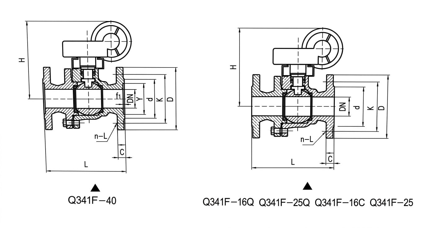
L = face-to-face length, H = overall height to the top of the handwheel; a dash means the value depends on the gear head selected for that size and is issued on the certified drawing. Flange drilling follows GB/T 9113 (RF) with JB/T 79 for PN40.
Structure Drawing
Design & Manufacturing Standards
- Design Standard: GB/T 12237 (flanged ball valves)
- Face-to-Face Dimensions: GB/T 12221
- Flange Standards: GB/T 9113 (RF), JB/T 79 for PN40
- Testing & Inspection: GB/T 13927
- Ductile Iron Material: QT450-10 per GB/T 1348
- Cast Steel Material: WCB per ASTM A216 / JB/T 9626
- Applicable International Standards: API 608, BS 5351, DIN 3357
Installation & Maintenance Guidelines
- Pipeline Preparation: Clean all pipe ends thoroughly before installation, removing welding slag, scale, rust, and any foreign debris. Flush the pipeline system to eliminate particles that could damage PTFE seats during first operation. Use gaskets rated for the specific pressure class (PN16/25/40) and temperature rating of the application.
- Installation Orientation: The Q341F worm gear ball valve can be installed in horizontal or vertical piping runs. For horizontal installation, ensure adequate clearance above the valve for the worm gear handwheel operation (refer to H dimension table). For vertical installation, orient the handwheel vertically upward for operator access. Avoid installing the gearbox in positions where condensate or debris can collect on the housing.
- Flange Alignment & Bolt Tightening: Align the valve flanges concentrically with the mating pipe flanges before inserting bolts. Tighten flange bolts in a cross-star pattern in multiple incremental passes to achieve uniform gasket compression. Never fully tighten one side first — uneven bolt loading causes body distortion that binds the floating ball against the seats, increasing operating torque and causing premature seat wear.
- Worm Gear Operation: Turn the handwheel clockwise to close the valve and counterclockwise to open it. The worm gear provides approximately 20:1 to 60:1 torque reduction depending on size, but do not apply excessive force at either end of travel — stop when resistance increases sharply indicating full seating. Do not use pipe wrenches or extension bars on the handwheel as this can damage the worm gear teeth.
- Lubrication Requirements: The worm gear gearbox is factory-filled with lubricating grease suitable for temperatures up to 200°C. Check the lubricant level annually and replenish if needed using lithium-based EP grease. For outdoor installations or high-temperature service, increase lubrication frequency to every 6 months. Do not overfill — excess grease can contaminate the valve interior through the stem area.
- Packing Adjustment & Replacement: If stem leakage is observed, carefully tighten the packing gland nut by no more than 1/8 turn increments while cycling the valve. Over-tightening scores the stainless steel stem and dramatically increases operating torque. Replace all packing rings during scheduled outages — never reuse old packing. Use PTFE V-ring or graphite packing as specified for the service temperature.
- Seat Inspection Interval: PTFE soft seats should be inspected every 12–24 months depending on cycle frequency and service severity. Look for signs of extrusion, cold-flow deformation, scratches, scoring, or compression set. Always replace both upstream and downstream seat rings together as a matched set. Verify proper seat groove cleanliness before installing new seats.
- Storage Before Installation: Store valves in a clean, dry indoor environment with both flange faces protected by plastic end caps. Keep valves in the partially open (approximately 10° open) position to relieve stress on the seats. Rotate the handwheel quarterly during extended storage periods to prevent gear lubricant settling and stem packing adhesion.
Application Fields
Gear-operated ball valves are specified where the line is large enough that a lever becomes hard work: Water Supply & Distribution Systems, Steam Heating Networks, Oil & Petroleum Transfer Lines, Chemical Process Industries, HVAC Central Plants, Power Plant Auxiliary Systems, Marine & Offshore Pipelines, Industrial Process Isolation, Fire Protection Systems, Municipal Infrastructure Projects. On these duties the self-locking gear also matters as a safety feature — an isolating valve that cannot be nudged off position by a pressure surge or by somebody leaning on a long handle.
What We Need to Quote Your Q341F Valves
- Size and pressure class: DN20–DN200, PN16, PN25 or PN40.
- Medium and design temperature: decides body material and whether PTFE soft seats are adequate.
- Body material: QT450-10 ductile iron, WCB cast steel or stainless on request.
- Gearhead preference: handwheel side, extension stem, or position indicator.
- Automation plans: tell us if an actuator may be fitted later so we include the mounting pad.
- Flange standard: GB/T 9113 or JB/T 79 standard; EN 1092 or ASME B16.5 on request.
- Documentation: EN 10204 3.1 certificates, test records, CE or API 6D for tenders.
Send the line size, design pressure and temperature and we will confirm whether the duty really needs a gear head, or whether a lever-operated Q41F is the more economic answer. Drawings are in the download center.
Frequently Asked Questions
Why put a gearbox on a ball valve at all?
Torque rises with the square of the bore, so a DN150 or DN200 ball valve against full differential pressure needs more hand effort than is safe or comfortable on a lever. The worm head reduces that effort by roughly 20 to 60 times depending on size, and it is self-locking, so line vibration cannot drive the valve off its seat.
Can the Q341F be actuated instead of geared?
Yes. The same body accepts a pneumatic rack-and-pinion or electric actuator on the standard mounting pad. Specify the failure position – fail closed, fail open or fail in the last position – and the service differential pressure, and we will size the actuator rather than the gear.
Is the Q341F a full bore valve?
Yes. The bore is matched to the inside diameter of the connecting pipe, so an open valve adds negligible pressure drop and the line can still be pigged or cleaned through it. Reduced bore is available when space or cost is the binding constraint.
What temperature can the PTFE seated version take?
Up to 200 degC on the soft-seat models listed in the specification table. Above that, PTFE cold-flows and the seat loses its preload, so a metal or reinforced seat is required and is engineered per enquiry rather than taken from a catalogue figure.
Does the worm gear need lubrication?
The gearbox ships filled with grease rated for the service temperature and needs checking about once a year, or every six months outdoors or in hot service. Replenish with a lithium EP grease and avoid overfilling, since excess grease can migrate down the stem area.
How much clearance does the gear head need?
Allow room for the handwheel to turn through its full arc plus access for the operator; the H dimension in the table is overall height to the top of the handwheel. For buried or high installations we can supply an extension stem and a raised pit access.
Get a Quote & Technical Support
Contact Gaoshan Valve for gear head selection, torque figures, CAD drawings and material certificates for your Q341F isolation duty. Reply within 24 hours from our overseas sales desk.