
Direct answer: A globe valve must be installed with media entering from below the disc (low inlet) and exiting above (high outlet). This “low-in, high-out” orientation keeps the bonnet and stuffing box isolated from line pressure when the valve is closed — improving sealing reliability, reducing external leakage, and allowing packing replacement without draining the line.
Flow direction is the most frequently overlooked detail in globe valve installation, and it is also the leading cause of premature valve failure. A reversed globe valve forces the bonnet assembly to bear full line pressure, works against the sealing surface, and turns a routine packing replacement into a full system shutdown.
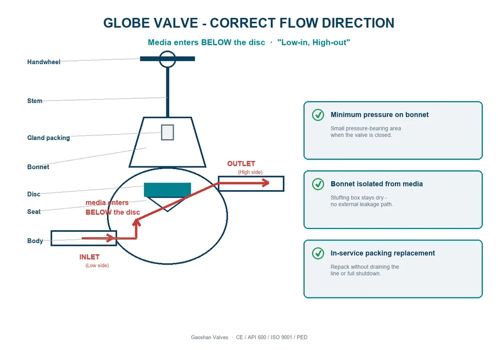
Three Engineering Benefits of Correct Flow Orientation
1. Pressure-Assisted Sealing with Minimum Bearing Area
With media entering below the disc, line pressure pushes the disc toward the seat in the closed position. The pressure-bearing area on the bonnet is minimized, and the sealing surface mates reliably with moderate hand torque. The result is a tight shut-off that does not rely on excessive gland load — extending stem and packing service life.
2. Bonnet Isolated from Media — Reduced Leakage Path
In the correct orientation, process fluid does not enter the valve body cavity above the disc. The bonnet-to-body joint and stuffing box remain dry and unpressurized when closed, eliminating the primary external leakage path — a measurable safety and environmental benefit in steam, chemical, and hydrocarbon service.
3. In-Service Maintenance Without Full Shutdown
Because the bonnet is isolated from line pressure in the closed position, the gland packing can be inspected and replaced while the valve remains installed and the line pressurized. This “repack-in-place” capability avoids the cost of system isolation, draining, and cooldown for routine packing service.
Flow Direction Comparison
| Factor | Correct (Low-in, High-out) | Reversed (High-in) |
|---|---|---|
| Shut-off sealing | Pressure-assisted, tight | Pressure opposes seal |
| Bonnet pressure load | Minimal when closed | Full line pressure |
| External leak risk | Low | High |
| Packing replacement | Possible in-service | Requires shutdown |
Recommended Globe Valve Models
| Model | Body | Pressure Class | DN Range | Standard |
|---|---|---|---|---|
| J41H-16C | Cast Steel WCB | PN16 | DN15–DN200 | GB/T 12235 |
| J41H-25C | Cast Steel WCB | PN25 | DN15–DN200 | GB/T 12235 |
| J41H-40C | Cast Steel WCB | PN40 | DN15–DN150 | GB/T 12235 |
| J41W-16P | Stainless Steel CF8 | PN16 | DN15–DN200 | GB/T 12235 |
Certifications: CE · API 600 · ISO 9001 · PED
Technical Specifications
- Body: WCB / CF8 / CF8M
- Disc & seat: 13Cr / SS304 / SS316 overlay
- Stem: 2Cr13 / SS304 / SS316
- End connection: Flanged RF (GB/T 9113, ASME B16.5)
- Temperature range: -29°C to 425°C (WCB)
- Leakage class: IV / V per ANSI/FCI 70-2
Frequently Asked Questions
Which direction should a globe valve be installed?
Media should enter from below the disc and exit above it — the “low-in, high-out” orientation.
What happens if a globe valve is installed backwards?
A reversed globe valve puts full line pressure on the bonnet, works against the sealing surface, and makes packing replacement impossible without shutdown.
Can a globe valve be repaired without shutting down the line?
Yes — for packing service. In the correct orientation, the stuffing box is unpressurized when closed, so packing can be replaced in-service.
How do I identify the correct inlet side on a globe valve?
Follow the flow-direction arrow cast on the body; the inlet is the lower port.
Get a Quote for Your Project
Send us your P&ID or valve datasheet — we will confirm the correct model, pressure class, and flow orientation for your piping specification.