
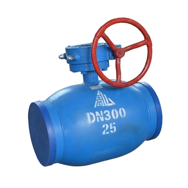
Welded Ball Valve Series
• 4 configurations: lever handle & worm gear, reduced & full bore
• Carbon steel body, Ss304 ball, PTFE+20%GC composite seats
• PN16–PN25, DN15–DN1400, ≤200°C
• Dish spring preload system — constant sealing force
Gaoshan Valve — Welded Ball Valve Series
Pressure: PN16–PN25 | Connection: Butt Welded | DN Range: DN15–DN1400 | Operation: Lever Handle / Worm Gear | Bore: Reduced & Full Bore | Type: Floating Ball Welded End Ball Valve
Natural Gas
Oil Products
Steam
Non-Corrosive Fluids
Core Strengths
Product Overview
The Gaoshan Valve welded ball valve series represents a comprehensive family of floating ball valves with butt-welded end connections designed for applications demanding permanent, leak-free integration into piping systems operating at temperatures up to 200°C and pressures up to PN25 (2.5 MPa). The product family encompasses four primary configurations: lever-handle operated reduced-bore for DN15–DN200, worm gear operated reduced-bore for DN50–DN1400, and worm gear operated full-bore for DN50–DN1400. All variants feature forged or cast carbon steel bodies with integral butt-weld end preparation, 304 stainless steel balls, PTFE+20%GC glass-carbon reinforced composite seat rings, fluorine rubber O-rings for secondary sealing, 2Cr13 martensitic stainless steel stems with anti-blowout design, and PTFE stem packing. The unique dish spring (60Si2MnA) preloading mechanism maintains constant seat contact pressure throughout the valve’s operational life, compensating for thermal cycling effects and gradual seat wear without requiring periodic retightening. Face-to-face dimensions follow established industry standards, and the butt-welded end connections eliminate flange-related leakage risks entirely — making this series the definitive choice for buried gas and oil pipelines, subsea installations, nuclear secondary loop systems, and high-integrity industrial process lines where external leakage is absolutely unacceptable.
Performance Specifications by Model
| Model Series | Nominal Pressure PN | Working Pressure (MPa) | Shell Test (MPa) | Seal Test (MPa) | Working Temp. (°C) | DN Range | Bore Type | Operation |
| PN16 Lever Handle | 16 | 1.6 | 2.4 | 1.76 | ≤200°C | 15–200 | Reduced | Lever Handle |
| PN25 Lever Handle | 25 | 2.5 | 3.75 | 2.75 | 15–200 | Reduced | Lever Handle | |
| PN16/25 Worm Gear (Reduced) | 16 / 25 | 1.6 / 2.5 | 2.4 / 3.75 | 1.76 / 2.75 | 50–1400 | Reduced | Worm Gear | |
| PN16/25 Worm Gear (Full Bore) | 16 / 25 | 1.6 / 2.5 | 2.4 / 3.75 | 1.76 / 2.75 | 50–1400 | Full Bore | Worm Gear |
Materials of Main Parts
| Part Name | Body & Bonnet (Body & Bonnet) | Ball (Ball) | Seal Ring (Seal Ring) | O-Ring (O-Ring) | Dish Spring (Dish Spring) | Stem (Stem) | Packing (Packing) | Handle (Handle) |
| Material | Carbon Steel (Carbon Steel) | Ss304 Stainless Steel | PTFE + 20% GC (PTFE + 20% Glass Carbon) | Fluorine Rubber (FKM Fluoroelastomer/Viton) | 60Si2MnA Spring Steel | 2Cr13 Martensitic Stainless Steel | PTFE | Carbon Steel (Carbon Steel) |
Main Dimensions — Lever Handle (Reduced Bore)
| DN15 | DN20 | DN25 | DN32 | DN40 | DN50 | DN65 | DN80 | DN100 | DN125 | DN150 | DN200 | |
| L (mm) | 140 | 152 | 165 | 178 | 190 | 300 | 300 | 300 | 320 | 323 | 350 | 400 |
| H (mm) | 100 | 112 | 123 | 150 | 150 | 127 | 160 | 171 | 215 | 250 | 272 | 300 |
| D (mm)* | 11 | 11 | 17 | 24 | 30 | 40 | 50 | 65 | 80 | 100 | 125 | 150 |
| D1 (mm)* | 19 | 27 | 34 | 42 | 48 | 60 | 76 | 89 | 114 | 140 | 168 | 219 |
| D2 (mm)* | 42 | 42 | 48 | 60 | 76 | 89 | 108 | 133 | 159 | 178 | 219 | 273 |
Main Dimensions — Worm Gear (Reduced Bore)
| DN50 | DN65 | DN80 | DN100 | DN125 | DN150 | DN200 | DN250 | DN300 | DN350 | |
| L (mm) | 300 | 300 | 300 | 320 | 323 | 350 | 395 | 516 | 635 | 762 |
| H (mm) | 160 | 170 | 180 | 200 | 220 | 260 | 300 | 350 | 450 | 550 |
| D (mm) | 40 | 50 | 65 | 80 | 100 | 125 | 150 | 200 | 250 | 300 |
| D1 (mm) | 60 | 76 | 89 | 114 | 140 | 168 | 219 | 273 | 324 | 376 |
| D2 (mm) | 80 | 108 | 133 | 159 | 178 | 219 | 273 | 351 | 426 | 508 |
| DN400 | DN450 | DN500 | DN600 | DN700 | DN800 | DN900 | DN1000 | DN1200 | DN1400 | |
| L (mm) | 838 | 914 | 991 | 1143 | 1346 | 1524 | 1727 | 1780 | 2100 | 2250 |
| H (mm) | 600 | 650 | 700 | 800 | 900 | 1055 | 1190 | 1110 | 1425 | 1550 |
| D (mm) | 337 | 337 | 385 | 487 | 590 | 686 | 779 | 900 | 956 | 1166 |
| D1 (mm) | 426 | 480 | 550 | 660 | 744 | 839 | 960 | 1045 | 1260 | 1450 |
| D2 (mm) | 560 | 560 | 657 | 810 | 962 | 1112 | 1255 | 1405 | 1650 | 1860 |
Main Dimensions — Worm Gear (Full Bore)
| DN50 | DN65 | DN80 | DN100 | DN125 | DN150 | DN200 | DN250 | DN300 | DN350 | |
| L (mm) | 300 | 300 | 300 | 320 | 323 | 350 | 395 | 516 | 635 | 762 |
| H (mm) | 170 | 180 | 200 | 200 | 260 | 300 | 350 | 450 | 550 | 550 |
| D (mm) | 50 | 65 | 65 | 100 | 125 | 150 | 200 | 250 | 300 | 300 |
| D1 (mm) | 60 | 76 | 89 | 114 | 140 | 150 | 219 | 273 | 324 | 376 |
| D2 (mm) | 108 | 133 | 159 | 178 | 219 | 273 | 351 | 426 | 508 |
| DN400 | DN450 | DN500 | DN600 | DN700 | DN800 | DN900 | DN1000 | DN1200 | DN1400 | |
| L (mm) | 838 | 914 | 991 | 1143 | 1346 | 1524 | 1727 | 1780 | 2100 | 2250 |
| H (mm) | 600 | 650 | 700 | 800 | 900 | 1055 | 1190 | 1110 | 1425 | 1550 |
| D (mm) | 385 | 436 | 487 | 590 | 684 | 779 | 900 | 900 | 1168 | 1360 |
| D1 (mm) | 457 | 508 | 560 | 660 | 744 | 839 | 960 | 1045 | 1260 | 1450 |
| D2 (mm) | 657 | 726 | 810 | 962 | 1140 | 1255 | 1405 | 1650 | 1860 | 2162 |
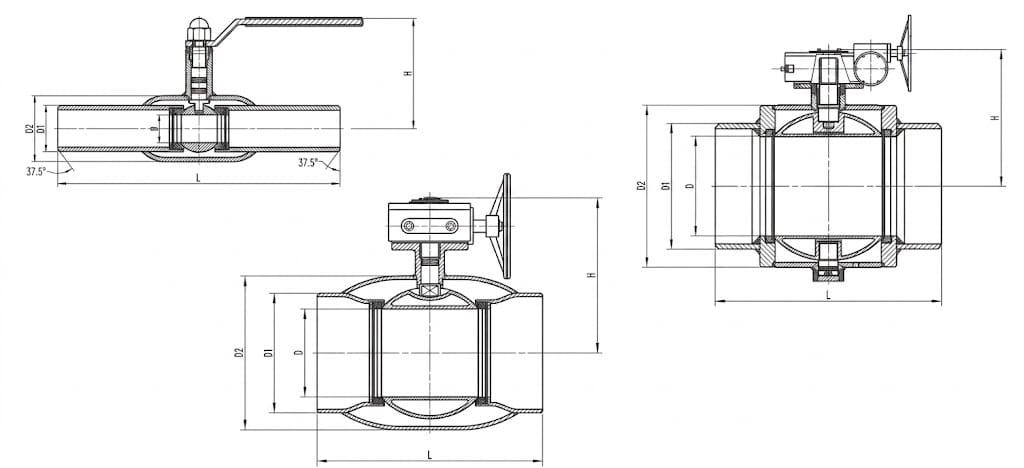
* L = Face-to-Face Length (overall length)including welded ends), H = Overall Height, D = Pipe OD / Bore Diameter, D1/D2 = Welding end diameters per GB/T standards. Note: Flanged connection dimension reference available on Page P95 (P95). Dimensions subject to manufacturing tolerances per applicable GB/T standards.
Structure Drawing
Design & Manufacturing Standards
- Design & Manufacture: GB/T 12237 (General-purpose Steel and Alloy Steel Ball Valves)
- Face-to-Face & Overall Dimensions: GB/T 12221 (Valve face-to-face dimensions)
- Butt-Welding Ends: GB/T 12224 / ASME B16.25 (Welding end dimensions for butt welding)
- Testing & Inspection: GB/T 13927 (Industrial Valves — Testing of Pressure Boundary)
- Body Material: Carbon Steel per GB/T 12228 / ASTM A105 / A350 LF2
- Ball Material: Ss304 per GB/T 1220 / ASTM A182 F304
- Stem Material: 2Cr13 per GB/T 1220 / ASTM A182 F6a Class 2
- Welding Procedure Qualification: NB/T 47014 / ASME Section IX
- Applicable International Standards: API 6D, BS 5351, ISO 14313
Installation & Commissioning Guidelines
- Pre-Welding Preparation: Verify that the valve body material grade matches the pipeline material specification to ensure compatible weldability characteristics. Confirm that the welding end bevel geometry on the valve conforms to the applicable standard (typically 30° bevel with 1.6 mm root face for wall thicknesses up to 22 mm). Check the valve’s internal cleanliness — debris introduced during shipping or storage must be removed before welding begins, as post-installation cleaning access is extremely limited once the valve is permanently welded into place.
- Pipeline Alignment & Fit-Up: Align the valve precisely between the two pipe sections using alignment clamps or external fixtures. Misalignment during fit-up introduces residual stress after welding that can distort the body cavity geometry, causing the ball to bind against the seats and increasing operating torque beyond design limits. Use internal optical alignment tools for DN300 and larger sizes where visual centerline verification becomes difficult. Maintain a uniform root gap of 2–4 mm around the circumference depending on the welding procedure specification (WPS).
- Welding Heat Input Control: Control interpass temperature strictly below 230°C for carbon steel bodies to prevent excessive grain growth in the heat-affected zone (HAZ) adjacent to the seat ring area. Excessive heat input can degrade the PTFE+20%GC composite seat material if conducted too close to the body cavity. Consider using heat sink materials (copper backing rings or wet rags wrapped around the body near the seat area) to draw heat away from temperature-sensitive internal components during the welding process.
- Weld Sequence & Stress Relief: Perform circumferential butt welds on both ends simultaneously (or alternate passes between ends) to balance shrinkage forces and minimize overall distortion. After completing all weld passes, allow controlled cooling to ambient temperature before removing alignment clamps. For critical applications or DN500 and above, consider post-weld heat treatment (PWHT) at 600–650°C for one hour per 25 mm of wall thickness to relieve residual welding stresses — consult the project welding engineer for specific PWHT requirements based on service conditions.
- Non-Destructive Examination (NDE): Perform 100% radiographic testing (RT) or ultrasonic testing (UT) on all butt welds connecting the valve to the pipeline, following the inspection level specified by the project code (typically RT per API 1104 for oil & gas pipelines or JB/T 4730.2 for general industrial applications). Acceptance criteria should reference the applicable code — typically no cracks, incomplete fusion, or slag inclusions exceeding specified limits. Document all NDE results in the commissioning record package.
- Pressure Testing Post-Installation: After completing all welding, NDE verification, and any required PWHT, conduct a hydrostatic shell test at 1.5 × PN (design pressure) holding for the minimum duration specified by the applicable code (typically 30 minutes for DN ≤ DN400, extended times for larger sizes). Follow with a low-pressure seat test (using air or nitrogen at 0.4–0.7 MPa) to verify bubble-tight shut-off capability. Record all test pressures, hold durations, and results in the installation documentation.
- Operational Break-In Procedure: Before placing the valve in normal service, cycle it through at least five full open-close cycles under low differential pressure conditions (system depressurized or bypass valve partially open). This break-in period allows the PTFE+20%GC composite seat surfaces to conform precisely to the ball contour and the dish spring preloading system to reach its equilibrium position. Monitor operating torque during each cycle — torque values should stabilize within ±15% after the initial break-in cycles. Abnormally increasing torque indicates possible contamination or misalignment issues requiring investigation.
- Buried Installation Protection: For underground pipeline installations, apply a complete corrosion protection coating system over the valve exterior and all exposed weld areas after NDE acceptance but before backfill. Ensure coating continuity over weld joints using compatible touch-up materials. Install a protective concrete encasement or mechanical shield over the worm gearbox/handle area to prevent damage from soil settlement, heavy equipment traffic, or excavation activities. Provide adequate clearance for future access to operate the valve — document the exact surface location marker coordinates in the as-built drawing set.
Application Fields
Natural Gas Distribution Mains
City Gate Stations
Power Plant Main Steam Lines
Subsea Pipeline Systems
Buried Water Distribution Networks
Offshore Platform Process Lines
Chemical Process Plants
Heating District Networks
LPG Storage & Transfer Facilities
Get a Quote & Technical Support
Contact Gaoshan Valve today for detailed dimension sheets, CAD drawings, welding procedure specifications (WPS/PQR packages), NDE requirements, material traceability documents (MTC), and customized welded ball valve solutions for your pipeline projects up to DN1400.