
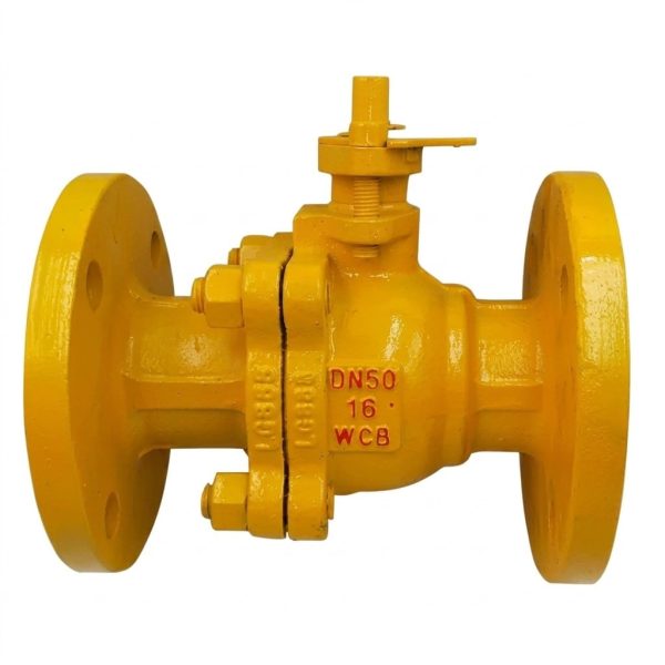
RQ41F Gas Ball Valve
• Dedicated gas ball valve for LPG / CNG / natural gas pipeline service
• 3 variants: RQ41F-16 / RQ41F-25 / RQ41F-40 covering PN16–PN40
• Full WCB cast steel construction, DN15–DN300, ≤100°C
• Reinforced PTFE seats — hydrocarbon-compatible, anti-swelling formula
• Anti-blowout stem, anti-static grounding, fire-safe compliant design
Gaoshan Valve — RQ41F Gas Ball Valve
Models: RQ41F-16 / RQ41F-25 / RQ41F-40 | Pressure: PN16–PN40 | Connection: Flanged | DN Range: DN15–DN300 | Type: Flanged Floating Gas Ball Valve for LPG / CNG Service
Compressed Natural Gas (CNG)
Natural Gas
Water
Petroleum Products
Core Strengths
Product Overview
The RQ41F series gas ball valve represents Gaoshan Valve’s dedicated solution for safe, reliable flow isolation in liquefied petroleum gas (LPG), compressed natural gas (CNG), and natural gas distribution pipelines operating at working temperatures up to 100°C. Available in three pressure class variants — RQ41F-16 (PN16, 1.6 MPa working pressure), RQ41F-25 (PN25, 2.5 MPa), and RQ41F-40 (PN40, 4.0 MPa) — covering nominal diameters from DN15 through DN300, the RQ41F addresses the full spectrum of gas transmission and distribution applications from residential meter stations through industrial process gas lines and city gate stations. The valve utilizes a proven floating ball design where the ball is supported solely by the two seat rings, allowing downstream movement under pressure that enhances sealing force against the outlet seat. All wetted parts are constructed from WCB cast steel bodies and bonnets (ASTM A216), 2Cr13 martensitic stainless steel balls and stems, and reinforced PTFE seat rings and packing specifically selected for long-term hydrocarbon gas compatibility. The anti-blowout stem design prevents stem ejection under any conceivable pressure condition, while the flanged end connections ensure secure, gasketed joint integrity compatible with standard ANSI/ASME and GB/T flange piping systems. Every RQ41F valve undergoes shell testing at 1.5× PN and seal testing at 1.1× PN per GB/T 13927 requirements before leaving the factory, with additional optional gas-tightness testing using helium or nitrogen tracer methods available upon request.
Performance Specifications by Model
| Model | Nominal Pressure PN | Working Pressure (MPa) | Shell Test Pressure (MPa) | Seal Test Pressure (MPa) | Working Temperature (°C) | Applicable Medium |
| RQ41F-16 | 16 | 1.6 | 3.8 | 2.8 | ≤100°C | Gas, Water, Petroleum, etc. |
| RQ41F-25 | 25 | 2.5 | 6.0 | 4.4 | ||
| RQ41F-40 | 40 | 4.0 | 9.6 | 7.04 |
Materials of Main Parts
| Part Name | Body & Bonnet | Stem | Packing | Ball | Seal Ring |
| Material | WCB Cast Steel (ASTM A216) | 2Cr13 Stainless Steel | Reinforced PTFE (Reinforced PTFE) | 2Cr13 Stainless Steel | Reinforced PTFE (Reinforced PTFE) |
Main Dimensions — PN16 & PN25 Series
| DN | 15 | 20 | 25 | 32 | 40 | 50 | 65 | 80 | 100 | 125 | 150 | 200 |
| L (mm) | 130 | 140 | 160 | 165 | 180 | 200 | 220 | 250 | 280 | 320 | 360 | 457 |
| H (mm) | 108 | 115 | 125 | 138 | 145 | 155 | 172 | 185 | 205 | 232 | 262 | 310 |
| W (mm) | 90 | 100 | 110 | 130 | 150 | 165 | 180 | 200 | 225 | 255 | 280 | 340 |
Main Dimensions — PN40 Series
| DN | 15 | 20 | 25 | 32 | 40 | 50 | 65 | 80 | 100 | 125 | 150 | 200 |
| L (mm) | 140 | 152 | 165 | 178 | 190 | 216 | 241 | 283 | 305 | 381 | 403 | 502 |
| H (mm) | 108 | 115 | 125 | 138 | 145 | 155 | 172 | 185 | 205 | 232 | 262 | 310 |
| W (mm) | 90 | 100 | 110 | 130 | 150 | 165 | 180 | 200 | 225 | 255 | 280 | 340 |
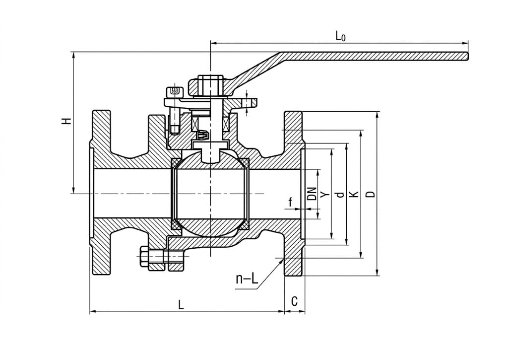
* L = Face-to-Face Length, H = Overall Height (to handle center), W = Handle Width (end to end). Flange connection dimensions refer to GB/T 9113 Flange Dimension Table. Dimensions are subject to manufacturing tolerance per GB/T standards.
Structure Drawing
Design & Manufacturing Standards
- Design & Manufacture: GB/T 12237 (General-purpose Steel and Alloy Steel Ball Valves)
- Face-to-Face Dimensions: GB/T 12221
- Flange End Dimensions: GB/T 9113 (Raised Face), JB/T 79 (for PN40)
- Testing & Inspection: GB/T 13927 (Shell & Seat Leakage Testing)
- Body Material Standard: WCB per ASTM A216 / GB/T 12229
- Stem & Ball Material: 2Cr13 per GB/T 1220
- Fire Safety (optional): API 607 / ISO 10497
- Gas Industry Reference: EN 331 (Gas Ball Valves), CGA V-1
- Anti-Static Requirement: Per GB/T 12237 Annex (electrical continuity test between ball and body)
Installation & Commissioning Guidelines
- Pre-Installation Safety Verification: Before installation, verify that the valve’s pressure rating (PN16/PN25/PN40) matches or exceeds the maximum expected pipeline operating pressure including surge conditions. Confirm the temperature rating (≤100°C) is compatible with the process conditions. Check that the reinforced PTFE seat material is chemically compatible with all media components that may contact the valve — especially important for gas mixtures containing hydrogen sulfide (H₂S) or other aggressive constituents.
- Pipeline Preparation & Cleaning: Thoroughly clean all pipe ends to remove welding slag, scale, rust, pipe dope residue, and loose particles. For gas pipelines, perform a purge cycle with inert gas (nitrogen) before introducing flammable gas to eliminate oxygen and debris. Install a temporary strainer upstream of the valve during initial commissioning to capture construction debris that could damage PTFE seat surfaces during first operation cycles.
- Gasket Selection: Use spiral wound gaskets or high-quality compressed fiber gaskets rated for the specific pressure class and gas service. Avoid asbestos-based gaskets. For LPG service, verify gasket material compatibility with propane/butane — graphite-filled or PTFE-faced gaskets are recommended. Ensure gaskets are properly seated and not pinched between flange faces during bolt tightening.
- Flange Bolt Tightening Procedure: Align valve flanges concentrically with mating pipe flanges. Insert bolts and hand-tighten nuts initially, then tighten in a cross-star (crisscross) pattern in minimum three incremental passes. Use a calibrated torque wrench following the bolt torque specification for the flange size and pressure class. Never fully tighten bolts on one side first — uneven loading causes body distortion that binds the floating ball and increases operating torque permanently.
- Handle Position & Locking: After installation, operate the valve through several open-close cycles to confirm smooth movement. In the closed position, verify that the handle aligns perpendicular to the pipeline axis indicating positive shut-off orientation. For safety-critical gas applications, consider installing a handle lock device or padlockable hasp on the handle in the required position (typically locked open or locked closed depending on the operational mode). Never leave the handle in a partially open position where the orientation is ambiguous.
- Leak Testing Protocol: Perform a pneumatic leak test using nitrogen or air at the specified seal test pressure (1.1 × PN) after installation. Apply a leak detection solution (soap water or commercial leak detector spray) to all flange joints, the stem packing area, and body-bonnet interface. Hold pressure for the minimum duration specified by local gas codes (typically 10–30 minutes) and monitor for any bubble formation or pressure decay. For LPG/CNG service, consider helium mass spectrometer testing for higher sensitivity requirements.
- Grounding & Anti-Static Verification: Verify electrical continuity between the ball, stem, and valve body using a multimeter (resistance should be less than 10 ohms). Ensure the valve body is properly bonded to the pipeline grounding system to prevent static charge accumulation that could create ignition sources in flammable gas environments. Document the continuity test results in the commissioning record.
- Operational Training: Train all personnel who will operate the RQ41F valve on proper handle operation — always move the handle smoothly through the full 90° travel without stopping mid-stroke. Emphasize that the valve is designed for fully-open or fully-closed service only and should not be used for throttling or flow regulation, as partial opening causes high-velocity gas flow across the seat that erodes PTFE material rapidly. Document emergency shutdown procedures clearly.
- Preventive Maintenance Schedule: Inspect the stem packing area quarterly for any signs of weepage or external leakage. Retighten packing gland nuts incrementally if minor leakage is detected (never over-tighten — excessive compression damages the stem and increases operating torque). Exercise the valve through full open-close cycles monthly during continuous service to prevent seat sticking. Perform a full internal inspection and seat replacement at intervals not exceeding 24 months for continuous gas service applications.
Application Fields
CNG Filling Stations
City Natural Gas Gate Stations
Residential Gas Metering Stations
Industrial Process Gas Lines
Gas Fired Power Plants
Petrochemical Plant Utility Systems
Oil Refinery Fuel Gas Networks
Biogas & Landfill Gas Collection
Ammonia & Refrigerant Gas Systems
Get a Quote & Technical Support
Contact Gaoshan Valve today for detailed dimension sheets, CAD drawings, material certificates (MTC), gas tightness test reports, and customized RQ41F gas ball valve solutions for your LPG, CNG, and natural gas pipeline requirements.