
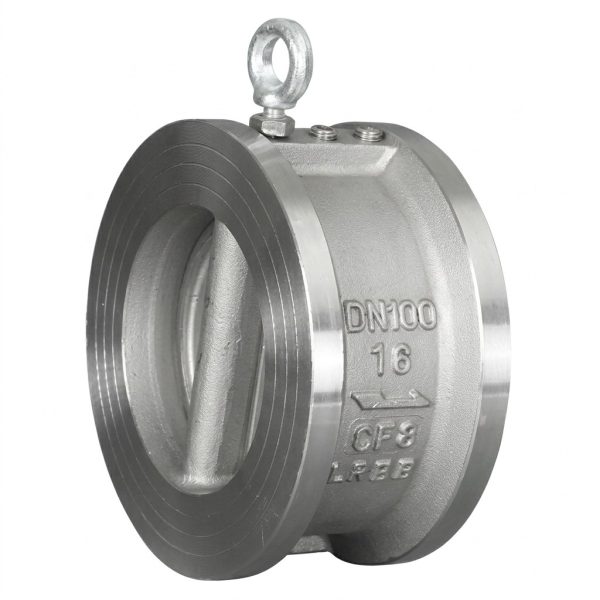
H76H/W wafer double disc swing check valve
• PN16/PN25/PN40 wafer double-disc swing check valve, DN50–DN600, ≤425°C
• Compact wafer alternative to H44 flanged swing check valve
• Spring-assisted dual semi-circular discs for rapid closure and low water hammer
• Three material grades: 2Cr13, 1Cr18Ni9Ti (304), 1Cr18Ni12Mo2Ti (316)
- • Fits between flanges; supports vertical and horizontal installation
Gaoshan Valve — H76H / H76W Wafer Double Disc Swing Check Valve
Model: H76H / H76W | Pressure: PN16–PN40 | Connection: Wafer (Between Flanges) | DN Range: DN50–DN600 | Installation: Vertical & Horizontal
Steam
Oil & Petroleum
Nitric Acid
Acetic Acid
Corrosive Media
Core Strengths
Product Overview
The H76H / H76W wafer double-disc swing check valve represents a space-saving evolution of traditional flanged swing check valves, engineered specifically to fit between standard pipe flanges using the existing bolt assembly. Its innovative twin semi-circular disc design features two spring-assisted swing plates mounted on central hinge pins within the ultra-slim wafer body. When forward pipeline pressure exceeds the spring preload, both discs swing inward and lie flat against the body interior—creating virtually zero obstruction to flow. Upon flow reversal, the combined action of reverse pressure and spring force snaps both discs shut in near-simultaneous fashion, achieving faster closure response than conventional single-disc swing valves while dramatically reducing water hammer effects. Available in sizes DN50 through DN600 with pressure ratings of PN16, PN25, and PN40, this series offers three all-stainless steel material grades: 2Cr13 for general-purpose water, steam, and petroleum service up to 425°C; 1Cr18Ni9Ti for nitric acid resistance; and 1Cr18Ni12Mo2Ti for severe corrosion environments including acetic acid. Both vertical and horizontal installation orientations are fully supported.
Performance Specifications
| Parameter | PN16 | PN25 | PN40 |
| Model (Carbon Steel) | H76H-16C | H76H-25 | H76H-40 |
| Model (Stainless 304) | H76W-16P | H76W-25P | H76W-40P |
| Model (Stainless 316) | H76W-16R | H76W-25R | H76W-40R |
| Nominal Pressure (MPa) | 1.6 | 2.5 | 4.0 |
| Shell Test Pressure (MPa) | 2.4 | 3.8 | 6.0 |
| Seal Test Pressure (MPa) | 1.8 | 2.8 | 4.4 |
| Max. Working Temperature | ≤425°C | ||
| Body Material | 2Cr13 / 1Cr18Ni9Ti / 1Cr18Ni12Mo2Ti Stainless Steel | ||
Material Selection Guide
| Material Grade | Valve Body | Disc | Best Suited For |
| 2Cr13 (Carbon Steel) | 2Cr13 | 2Cr13 | Water, Steam, Oil, Petroleum |
| 1Cr18Ni9Ti (AISI 304) | 1Cr18Ni9Ti | 1Cr18Ni9Ti | Nitric Acid Environments |
| 1Cr18Ni12Mo2Ti (AISI 316) | 1Cr18Ni12Mo2Ti | 1Cr18Ni12Mo2Ti | Nitric Acid, Acetic Acid, Severe Corrosive Media |
Main Dimensions & Weights
| DN (mm) | PN10 / PN16 | PN25 | PN40 | ||||||
| L (mm) | D (mm) | Weight (kg) | L (mm) | D (mm) | Weight (kg) | L (mm) | D (mm) | Weight (kg) | |
| 50 | 60 | 109 | 1.8 | 60 | 109 | 2.0 | 60 | 109 | 2.4 |
| 65 | 67 | 129 | 2.6 | 67 | 129 | 3.2 | 67 | 129 | 3.8 |
| 80 | 73 | 144 | 4.2 | 73 | 144 | 4.8 | 73 | 144 | 5.6 |
| 100 | 73 | 164 | 5.2 | 73 | 170 | 6.0 | 73 | 170 | 7.5 |
| 125 | 83 | 194 | 6.7 | 83 | 198 | 9.0 | 83 | 198 | 11 |
| 150 | 98 | 220 | 9.4 | 98 | 228 | 12 | 98 | 228 | 15 |
| 200 | 127 | 275 | 18.7 | 127 | 298 | 22 | 127 | 293 | 27 |
| 250 | 146 | 333 | 29.4 | 146 | 343 | 38 | 146 | 355 | 48 |
| 300 | 181 | 388 | 48.5 | 181 | 403 | 54 | 181 | 420 | 78 |
| 350 | 184 | 448 | 66 | 184 | 480 | 80 | 184 | 480 | 116 |
| 400 | 198 | 498 | 90 | 198 | 520 | 118 | 198 | 549 | 152 |
| 450 | 203 | 558 | 130 | — | |||||
| 500 | 219 | 630 | 186 | — | |||||
| 600 | 222 | 734 | 298 | — | |||||
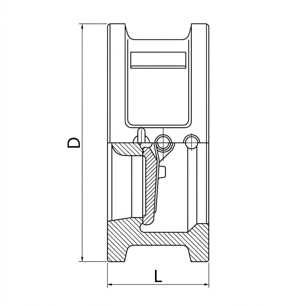
* L = Face-to-Face Length, D = Outer Diameter. All values are for reference only. Contact us for detailed drawings for your specific model.
Structure Drawing
Design & Manufacturing Standards
- Design Standard: GB/T 12236
- Face-to-Face Dimensions: GB/T 12221
- Flange Standards: GB/T 9113, JB/T 79, HG/T 20592
- Testing & Inspection: GB/T 13927, JB/T 9092
- Applicable International Standards: EN 13709, API 594, ISO 5752 (optional)
Installation & Maintenance Guidelines
- Wafer Mounting: Install the wafer valve between two flanges using the same bolt set. Ensure the valve bore aligns perfectly with the pipeline centerline. Use full-face gaskets on each side for proper sealing between flange faces.
- Flow Direction: Verify correct orientation against the flow direction arrow marked on the valve body. Incorrect installation direction will prevent proper disc operation and may cause damage under reverse pressure.
- Dual Orientation Capability: Can be installed on both horizontal and vertical piping without performance degradation. For vertical installations, ensure upward flow direction for optimal disc swing action.
- Bolt Tightening Sequence: Use a star-pattern torque sequence to compress the wafer body evenly between flanges. Avoid over-torquing which may distort the thin-profile body and impede free disc movement on hinge pins.
- Maintenance: Periodically inspect both swing discs, hinge pins, and sealing surfaces for wear, corrosion, or debris buildup. Check spring preload tension. Replace worn components as a matched pair to maintain balanced disc operation.
Application Fields
Cooling Tower Systems
Industrial Circulating Water
Chemical Processing Plants
HVAC & District Heating
Power Generation Cooling Water
Marine Ballast Systems
Fire Protection Networks
Get a Quote & Technical Support
Contact Gaoshan Valve today for detailed dimension sheets, CAD drawings, material certifications, and customized wafer double-disc check valve solutions for your large-diameter pipeline project.