
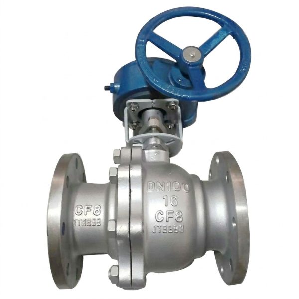
Q341F Worm Gear Operated Ball Valve
• Worm gear operated flanged ball valve for low-torque pipeline control
• Bi-directional sealing with PTFE/hard seat options (≤150℃ / ≤450℃)
• PN16/25/40 pressure ratings, DN15-DN300 full size range
• Fire-safe & anti-static design for industrial applications
• WCB/304/316 materials compatible with water, gas, oil and corrosive media
Gaoshan Valve — Q341F Worm Gear Operated Ball Valve
Models: Q341F-16Q / Q341F-16C / Q341F-25Q / Q341F-25 / Q341F-40 | Pressure: PN16–PN40 | Connection: Flanged | DN Range: DN20–DN200 | Type: Worm Gear Operated Floating Ball Valve
Steam
Oil Products
Petroleum
Non-Corrosive Fluids
Core Strengths
Product Overview
The Q341F series worm gear operated floating ball valve is an engineered quarter-turn shut-off device designed for reliable isolation of water, steam, oil, petroleum, and non-corrosive fluid pipelines requiring manual operation on larger-diameter or higher-pressure installations. Building upon the proven Q41F flanged ball valve platform, the Q341F adds an integral worm gear actuator that reduces required operating torque while maintaining precise 90-degree open/close positioning. The worm gear’s self-locking characteristic prevents unintended valve position changes caused by vibration or line pressure fluctuations, providing secure isolation safety. Available in five model variants spanning three pressure classes (PN16, PN25, PN40) and two body material families (QT450 ductile iron for Q/Q models, WCB cast steel for C models), the Q341F covers applications from general-purpose water distribution through heavy-duty industrial process systems. All models share identical internal component specifications including 2Cr13 or 304 stainless steel balls and stems, PTFE soft seat rings, and anti-blowout stem designs. Face-to-face dimensions comply with GB/T 12221 standards, and flange connections follow GB/T 9113 / JB/T 79 specifications. Every valve undergoes rigorous shell testing at 1.5×PN and seat testing at 1.1×PN per GB/T 13927 requirements.
Performance Specifications by Model
| Model | PN | Working Pressure (MPa) | Shell Test (MPa) | Seal Test (MPa) | Body Material | Max. Temp. |
| Q341F-16Q | 16 | 1.6 | 2.4 | 1.76 | Ductile Iron QT450 | ≤200°C |
| Q341F-16C | 16 | 1.6 | 2.4 | 1.76 | WCB Cast Steel | ≤200°C |
| Q341F-25Q | 25 | 2.5 | 3.75 | 2.75 | Ductile Iron QT450 | ≤200°C |
| Q341F-25 | 25 | 2.5 | 3.75 | 2.75 | WCB Cast Steel | ≤200°C |
| Q341F-40 | 40 | 4.0 | 6.0 | 4.4 | WCB Cast Steel | ≤200°C |
Materials of Main Parts
| Part Name | Material (Q Models) | Material (C Models) |
| Body & Bonnet | Ductile Cast Iron QT450-10 | Cast Carbon Steel WCB (ASTM A216) |
| Ball | Martensitic Stainless Steel 2Cr13 | Austenitic Stainless Steel 304 |
| Stem | Martensitic Stainless Steel 2Cr13 | Austenitic Stainless Steel 304 |
| Seat Ring | PTFE (Polytetrafluoroethylene) — Soft Seated | |
| Packing / Gasket | PTFE Packing + Flexible Graphite Gasket | |
| Stem Bearing | Bronze Bushing / Composite Bearing | |
| Worm Gear Box Housing | Ductile Iron / Aluminum Alloy Die-Cast | |
| Worm Gear Set | Carbon Steel Worm + Bronze Worm Wheel | |
Main Dimensions — PN16 & PN25 Series
| DN | 20 | 25 | 32 | 40 | 50 | 65 | 80 | 100 | 125 | 150 | 200 |
| L (mm) | 140 | 160 | 165 | 180 | 200 | 220 | 250 | 280 | 320 | 360 | 457 |
| H (mm)* | — | — | — | — | — | — | 483 | 613 | 655 | — | — |
Main Dimensions — PN40 Series
| DN | 20 | 25 | 32 | 40 | 50 | 65 | 80 | 100 | 125 | 150 | 200 |
| L (mm) | 152 | 165 | 178 | 190 | 216 | 241 | 283 | 305 | 381 | 403 | 502 |
| H (mm)* | — | — | — | — | — | — | 483 | 613 | 655 | — | — |
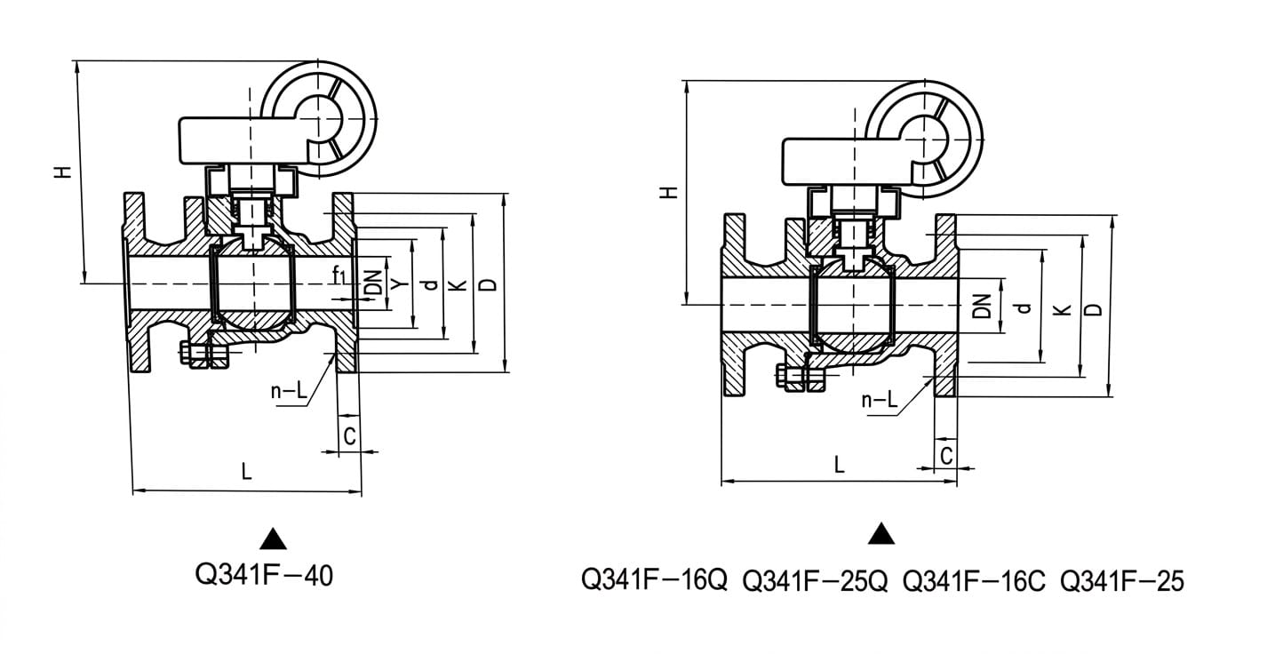
* L = Face-to-Face Length, H = Overall Height (to top of handwheel). Flange connection dimensions refer to GB/T 9113 Flange Dimension Table. Technical specifications and main part materials are identical to corresponding Q41F-16Q, Q41F-16C, Q41F-25Q, Q41F-25, and Q41F-40 models.
Structure Drawing
Design & Manufacturing Standards
- Design Standard: GB/T 12237 (Flanged Ball Valves)
- Face-to-Face Dimensions: GB/T 12221
- Flange Standards: GB/T 9113 (RF), JB/T 79 (for PN40)
- Testing & Inspection: GB/T 13927
- Ductile Iron Material: QT450-10 per GB/T 1348
- Cast Steel Material: WCB per ASTM A216 / JB/T 9626
- Applicable International Standards: API 608, BS 5351, DIN 3357
Installation & Maintenance Guidelines
- Pipeline Preparation: Clean all pipe ends thoroughly before installation, removing welding slag, scale, rust, and any foreign debris. Flush the pipeline system to eliminate particles that could damage PTFE seats during first operation. Use gaskets rated for the specific pressure class (PN16/25/40) and temperature rating of the application.
- Installation Orientation: The Q341F worm gear ball valve can be installed in horizontal or vertical piping runs. For horizontal installation, ensure adequate clearance above the valve for the worm gear handwheel operation (refer to H dimension table). For vertical installation, orient the handwheel vertically upward for operator access. Avoid installing the gearbox in positions where condensate or debris can collect on the housing.
- Flange Alignment & Bolt Tightening: Align the valve flanges concentrically with the mating pipe flanges before inserting bolts. Tighten flange bolts in a cross-star pattern in multiple incremental passes to achieve uniform gasket compression. Never fully tighten one side first — uneven bolt loading causes body distortion that binds the floating ball against the seats, increasing operating torque and causing premature seat wear.
- Worm Gear Operation: Turn the handwheel clockwise to close the valve and counterclockwise to open it. The worm gear provides approximately 20:1 to 60:1 torque reduction depending on size, but do not apply excessive force at either end of travel — stop when resistance increases sharply indicating full seating. Do not use pipe wrenches or extension bars on the handwheel as this can damage the worm gear teeth.
- Lubrication Requirements: The worm gear gearbox is factory-filled with lubricating grease suitable for temperatures up to 200°C. Check the lubricant level annually and replenish if needed using lithium-based EP grease. For outdoor installations or high-temperature service, increase lubrication frequency to every 6 months. Do not overfill — excess grease can contaminate the valve interior through the stem area.
- Packing Adjustment & Replacement: If stem leakage is observed, carefully tighten the packing gland nut by no more than 1/8 turn increments while cycling the valve. Over-tightening scores the stainless steel stem and dramatically increases operating torque. Replace all packing rings during scheduled outages — never reuse old packing. Use PTFE V-ring or graphite packing as specified for the service temperature.
- Seat Inspection Interval: PTFE soft seats should be inspected every 12–24 months depending on cycle frequency and service severity. Look for signs of extrusion, cold-flow deformation, scratches, scoring, or compression set. Always replace both upstream and downstream seat rings together as a matched set. Verify proper seat groove cleanliness before installing new seats.
- Storage Before Installation: Store valves in a clean, dry indoor environment with both flange faces protected by plastic end caps. Keep valves in the partially open (approximately 10° open) position to relieve stress on the seats. Rotate the handwheel quarterly during extended storage periods to prevent gear lubricant settling and stem packing adhesion.
Application Fields
Steam Heating Networks
Oil & Petroleum Transfer Lines
Chemical Process Industries
HVAC Central Plants
Power Plant Auxiliary Systems
Marine & Offshore Pipelines
Industrial Process Isolation
Fire Protection Systems
Municipal Infrastructure Projects
Get a Quote & Technical Support
Contact Gaoshan Valve today for detailed dimension sheets, CAD drawings, material certificates, and customized Q341F worm gear operated ball valve solutions for your isolation and control applications.