
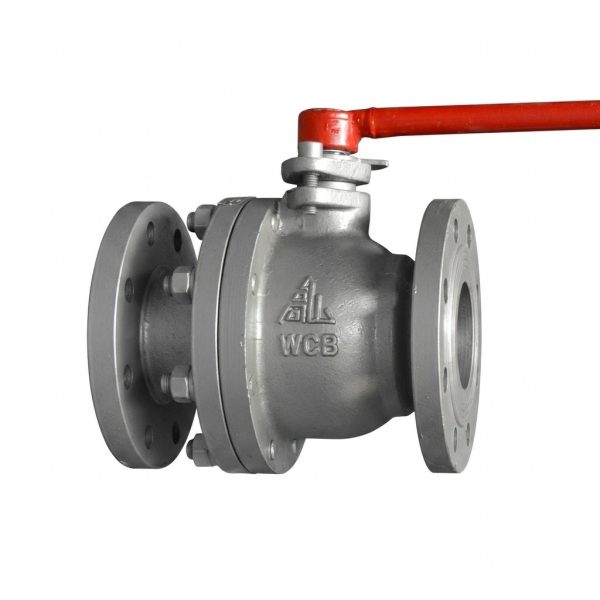
Q41F Ball Valve
– Floating ball design with PTFE soft seat rings for bubble-tight shut-off across PN16, PN25, PN40, and PN63 pressure classes
– Multi-material body options: QT450 ductile iron (16Q/25Q), WCB cast steel (16C/25/40), and stainless steel CF8 (16P)
– Anti-blowout stem with dual PTFE packing prevents external leakage and stem ejection under pressure
– Quarter-turn manual lever operation with low torque — gear actuator optonal for DN125 and above
– Suitable for water, steam, oil, petroleum, and non-corrosive fluids at temperatures up to 200°C
Gaoshan Valve — Q41F Flanged Ball Valve
Models: Q41F-16Q / 16C / 25Q / 25 / 40 / 16P | Pressure: PN16–PN63 | Connection: Flanged | DN Range: DN20–DN200 | Type: Floating Ball, Manual Lever Operated
Steam
Oil Products
Petroleum
Non-Corrosive Fluids
Core Strengths
Product Overview
The Q41F flanged ball valve series is a versatile quarter-turn shut-off valve designed for reliable on-off flow control in water, steam, oil, petroleum, and non-corrosive fluid systems operating at temperatures up to 200°C. Featuring a floating ball design with PTFE soft seat rings, the Q41F delivers bubble-tight shutoff with minimal operating torque. The series encompasses seven model variants covering four pressure classes (PN16 through PN63) and three body material options: ductile cast iron for economical water and oil service (Q41F-16Q/25Q), WCB cast steel for demanding steam and high-pressure applications (Q41F-16C/25/40), and stainless steel for corrosive environments (Q41F-16P). Available sizes range from DN20 to DN200 depending on pressure class, with standard flanged end connections conforming to GB/T 9113 and JB/T 79 flange drilling patterns. The anti-blowout stem design with dual PTFE packing ensures leak-free operation and enhanced safety. Whether used in water supply networks, steam boiler feed lines, oil transfer stations, or industrial process loops, the Q41F ball valve provides dependable isolation performance backed by rigorous factory testing to GB/T 13927 standards.
Performance Specifications
| Parameter | Q41F-16Q / 16C | Q41F-25Q / 25 | Q41F-40 |
| Nominal Pressure (PN) | 16 (1.6 MPa) | 25 (2.5 MPa) | 40 (4.0 MPa) |
| Shell Test Pressure | 2.4 MPa | 3.8 MPa | 6.0 MPa |
| Seal Test Pressure | 1.8 MPa | 2.8 MPa | 4.4 MPa |
| Working Temperature | ≤200°C | ||
| Suitable Media | Water, Steam, Oil, Petroleum, Non-corrosive Fluids | ||
| Connection Type | Flanged (GB/T 9113, JB/T 79, HG/T 20592) | ||
| Operation Mode | Manual Lever Handle (Gear optional for DN125+) | ||
| Seat Material | PTFE (Polytetrafluoroethylene) | ||
Materials of Main Parts
| Model Series | Body & Bonnet | Ball | Stem | Seat Ring / Packing |
| Q41F-16Q / Q41F-25Q | Ductile Cast Iron (QT450-10) | 2Cr13 Martensitic Steel | 2Cr13 / Stainless Steel | PTFE (Polytetrafluoroethylene) |
| Q41F-16C / Q41F-25 / Q41F-40 | WCB Cast Steel (ASTM A216) | |||
| Q41F-16P | Stainless Steel (CF8 / 304) | 304 Stainless | 304 Stainless |
Main Dimensions & Weights
| PN | Dim | Nominal Size DN (mm) | ||||||||||
| 20 | 25 | 32 | 40 | 50 | 65 | 80 | 100 | 125 | 150 | 200 | ||
| 16 | L (mm) | 140 | 160 | 165 | 180 | 200 | 220 | 250 | 280 | 320 | 360 | 457 |
| H (mm) | 105 | 110 | 115 | 122 | 122 | 130 | 142 | 152 | 162 | 182 | 312 | |
| L0 (mm) | 150 | 150 | 150 | 160 | 160 | 200 | 350 | 350 | 400 | 400 | 800 | |
| Weight (kg) | 4 | 5 | 9 | 10 | 13 | 17 | 20 | 34 | 47 | 51 | 120 | |
| 25 | L (mm) | 140 | 160 | 165 | 180 | 200 | 220 | 250 | 280 | 320 | 360 | 457 |
| H (mm) | 105 | 110 | 115 | 122 | 122 | 130 | 142 | 152 | 162 | 260 | 312 | |
| L0 (mm) | 150 | 150 | 150 | 160 | 160 | 200 | 350 | 350 | 400 | 600 | 800 | |
| Weight (kg) | 4 | 5 | 9 | 10 | 14 | 15 | 24 | 38 | 52 | 93 | 120 | |
| 40 | L (mm) | 152 | 185 | 178 | 190 | 230 | 216 | 283 | 305 | 380 | 403 | 502 |
| H (mm) | 185 | 85 | 110 | 135 | 230 | 142 | 173 | 183 | 250 | 340 | 395 | |
| L0 (mm) | 190 | 190 | 220 | 250 | 250 | 270 | 350 | 400 | 450 | 500 | 1500 | |
| Weight (kg) | 5 | 6 | 11 | 12 | 17 | 18 | 29 | 45 | 60 | 107 | 138 | |
| 63 | L (mm) | 190 | 216 | 241 | 250 | 280 | 320 | 360 | 450 | 500 | — | — |
| H (mm) | 216 | 95 | 112 | 132 | 145 | 169 | 182 | 302 | — | 330 | — | |
| L0 (mm) | 229 | 229 | 241 | 250 | 270 | 350 | 350 | 600 | 800 | 1000 | — | |
| Weight (kg) | 5 | 6 | 11 | 15 | 20 | 22 | 35 | 53 | 69 | 123 | — | |
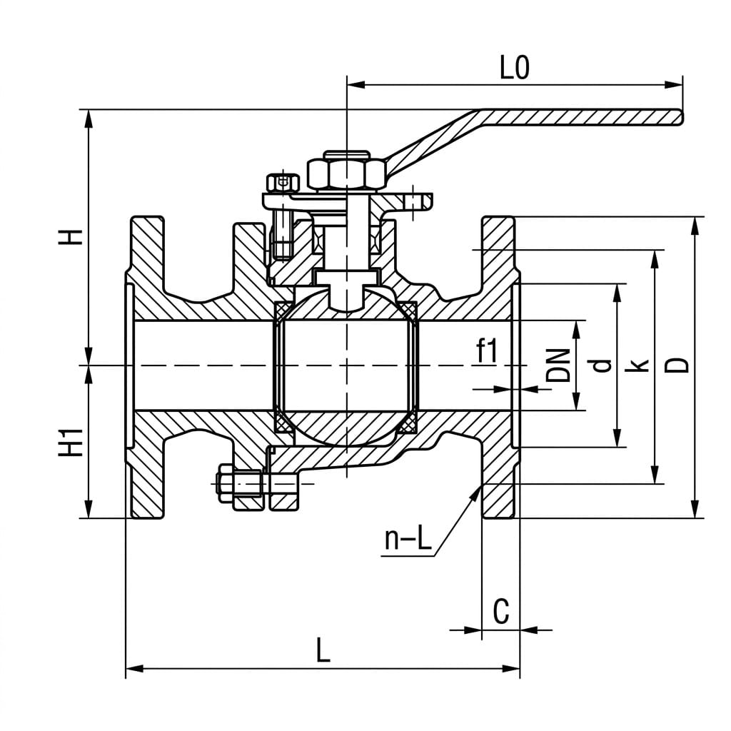
* L = Face-to-Face Length, H = Height, L0 = Handle Length. All values are for reference only. Dimensions may vary slightly by manufacturing batch. Contact us for certified drawings.
Structure Drawing
Design & Manufacturing Standards
- Design Standard: GB/T 12237 (Ball Valves)
- Face-to-Face Dimensions: GB/T 12221
- Flange Standards: GB/T 9113, JB/T 79, HG/T 20592, ASME B16.5 (optional)
- Testing & Inspection: GB/T 13927, API 598, ISO 5208
- Ductile Iron Material: QT450-10 per GB/T 1348
- Cast Steel Material: WCB per ASTM A216
- Applicable International Standards: API 6D, BS 5351 (optional)
Installation & Maintenance Guidelines
- Pipeline Preparation: Ensure pipeline ends are clean, free of welding slag, scale, and foreign debris before installation. Flush the pipeline thoroughly to remove any particles that could damage the PTFE seats during initial operation. Use proper gaskets matching the flange face type (RF or RJ).
- Installation Position: Ball valves can be installed in horizontal or vertical pipelines. For vertical installations, ensure upward flow direction. Avoid installing the valve where water can accumulate on top of the bonnet in outdoor applications. Provide adequate support to prevent excessive pipe load on the valve body.
- Flow Direction: While most Q41F models are bidirectional, verify the cast arrow marking on the body. For unidirectional designs, install so that flow follows the arrow direction. Incorrect orientation may cause seat damage or leakage under high differential pressure.
- Flange Bolt Tightening: Align flange faces evenly before tightening bolts. Follow a cross-pattern tightening sequence in multiple passes to achieve uniform gasket compression. Do not fully tighten one side first as this causes body distortion and ball binding. Refer to bolt torque tables for the specific bolt grade and gasket material.
- Operating Instructions: Fully open or close the valve only — never use a ball valve for intermediate throttling as partially exposed seats will erode quickly from high-velocity flow. When opening, pause briefly at mid-position (45°) to equalize pressure across the ball before completing the turn. Always close slowly to prevent water hammer in liquid-filled systems.
- Packing Maintenance: Periodically check the stem packing area for signs of weeping or external leakage. If minor leakage occurs, gently retighten the packing gland nut by no more than 1/6 turn at a time while cycling the handle. Over-tightening will score the stem and increase operating torque. Replace packing rings if leakage persists.
- Seat Replacement: PTFE seats are subject to wear and cold-flow over extended service life, especially in high-cycle applications. Inspect seats annually for deformation, scratches, or compression set. Replace seat rings if the valve fails to hold seal test pressure. Always replace both upstream and downstream seats together.
- Lubrication: Apply a thin film of compatible grease (silicone-based or PTFE-compatible) to the ball surface and seat grooves during reassembly after maintenance. Never use hydrocarbon-based lubricants that may degrade PTFE materials. Lubricate stem threads periodically to maintain smooth handle operation.
Application Fields
Steam Boiler Feedwater Systems
Oil Refinery Process Pipelines
Petroleum Storage Terminals
Chemical Processing Plants
HVAC Heating & Cooling Systems
Fire Protection Systems
Industrial Compressed Air Lines
Marine & Shipboard Piping
Power Generation Auxiliaries
Get a Quote & Technical Support
Contact Gaoshan Valve today for detailed dimension sheets, CAD drawings, material certificates, and customized Q41F ball valve solutions for your water, steam, oil, or industrial pipeline project.