

H41H Lift Check Valve
- Product Model: H41H Series Flanged Lift Check Valve (H41H-16 / 16Q / 16C / 25Q / 25)
- Pressure Rating: PN16 (1.6MPa) / PN25 (2.5MPa)
- Body Material: Gray Cast Iron / Ductile Iron / WCB Cast Steel
- Sealing Material: 2Cr13 Stainless Steel (with optional hard alloy overlay)
- Applicable Media: Water, Steam, Oil, and weak corrosive media
- Working Temperature: ≤200℃ / ≤300℃ / ≤425℃ (depending on material)
- Connection Type: Flanged (compliant with GB/T 9113 standard)
- Core Function: Automatically prevents medium backflow to protect pumps and equipment
- Installation: Suitable for vertical/horizontal pipelines, with direction marked on valve body
- Application Scenarios: Petroleum, chemical, power, water treatment and industrial pipeline systems
Gaoshan Valve — H41H Flanged Lift Check Valve
Model: H41H-16 / H41H-16Q / H41H-16C / H41H-25Q / H41H-25 | Pressure: PN16 / PN25 | Connection: Flanged | Medium: Water, Steam, Oil
Steam
Oil
Weak Corrosive Media
Core Strengths
Product Overview
H41H flanged lift check valve is an automatic valve designed to prevent medium backflow in pipeline systems. It operates solely by the force of the medium flow—opening when forward flow pressure is applied and closing automatically when flow stops or reverses. This check valve is widely used at pump outlets and critical pipeline nodes to protect equipment from reverse flow damage. With a robust flanged connection and multiple body material options, it meets the demands of water treatment, power plants, petrochemical, and general industrial applications.
Performance Specifications
| Model | Nominal Pressure (MPa) | Shell Test (MPa) | Seal Test (MPa) | Max. Temperature | Applicable Medium |
| H41H-16 | 1.6 | 2.4 | 1.8 | ≤200°C (Gray Cast Iron) | Water, Steam, Oil |
| H41H-16Q / 25Q | 1.6 / 2.5 | 2.4 / 3.8 | 1.8 / 2.8 | ≤300°C (Ductile Iron) | Water, Steam, Oil |
| H41H-16C / 25 | 1.6 / 2.5 | 2.4 / 3.8 | 1.8 / 2.8 | ≤425°C (WCB Cast Steel) | Water, Steam, Oil |
Main Component Materials
| Model | Valve Body / Bonnet | Valve Seat / Disc |
| H41H-16 | Gray Cast Iron | 2Cr13 Stainless Steel |
| H41H-16Q / 25Q | Ductile Iron | 2Cr13 Stainless Steel |
| H41H-16C / 25 | WCB Cast Steel | 2Cr13 Stainless Steel |
Main Dimensions & Weights
| Pressure | DN (mm) | Face-to-Face L (mm) | Height H (mm) | Weight (kg) |
| PN16 | 40 | 200 | 96 | 8 |
| 50 | 230 | 103 | 11 | |
| 65 | 290 | 150 | 14 | |
| 80 | 310 | 156 | 22 | |
| 100 | 350 | 166 | 32 | |
| 125 | 400 | 201 | 60 | |
| 150 | 480 | 238 | 95 | |
| 200 | 600 | 268 | 120 | |
| PN25 | 25 | 160 | 90 | 6 |
| 32 | 180 | 110 | 9 | |
| 40 | 200 | 115 | 11 | |
| 50 | 230 | 126 | 14 | |
| 65 | 290 | 165 | 25 | |
| 80 | 310 | 165 | 32 | |
| 100 | 350 | 180 | 45 |
* Dimensions are for reference only. Contact us for detailed drawings for your specific model.
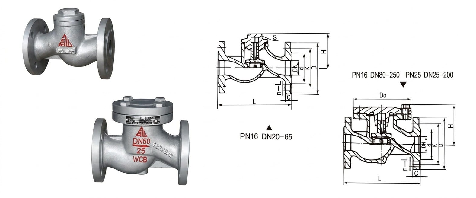
Structure Drawing
Design & Manufacturing Standards
- Design Standard: GB/T 12235
- Face-to-Face Dimensions: GB/T 12221
- Flange Standards: GB/T 9113, JB/T 79, HG/T 20596
- Testing & Inspection: GB/T 13927, JB/T 9092
- Applicable International Standards: EN 13709, EN 558 (optional)
Installation & Maintenance Guidelines
- Installation Requirements: Do not let the check valve bear pipeline weight; large valves require independent support to avoid excessive pipeline stress.
- Flow Direction: Install the valve with the medium flow direction matching the arrow marked on the valve body.
- Pipeline Orientation: Vertical disc lift check valves must be installed on vertical pipelines; horizontal disc types on horizontal pipelines.
- Maintenance Tips: Keep the valve clean during operation; regularly inspect sealing surfaces for wear to ensure reliable anti-backflow performance.
Application Fields
Power Plants
Petrochemical
Oil & Gas
HVAC Systems
General Industry
Get a Quote & Technical Support
Contact Gaoshan Valve today for detailed dimension sheets, CAD drawings, and customized solutions for your pipeline system.