
DN125 Steam Pressure Reducing Valve Station: Engineered Control for High-Pressure Steam Networks
PRODUCT RELEASE | INDUSTRIAL STEAM SYSTEMS
A factory-assembled, pre-piped pressure management solution delivering precise downstream pressure regulation, condensate elimination and system protection in a single, installation-ready skid.
Overview
Steam is one of the most widely used heat-transfer media in modern industry. However, boiler systems and long-distance steam mains operate at pressures far exceeding what most end-use processes can safely tolerate. Delivering steam at the correct pressure — consistently, reliably and safely — is both a process requirement and a safety imperative.
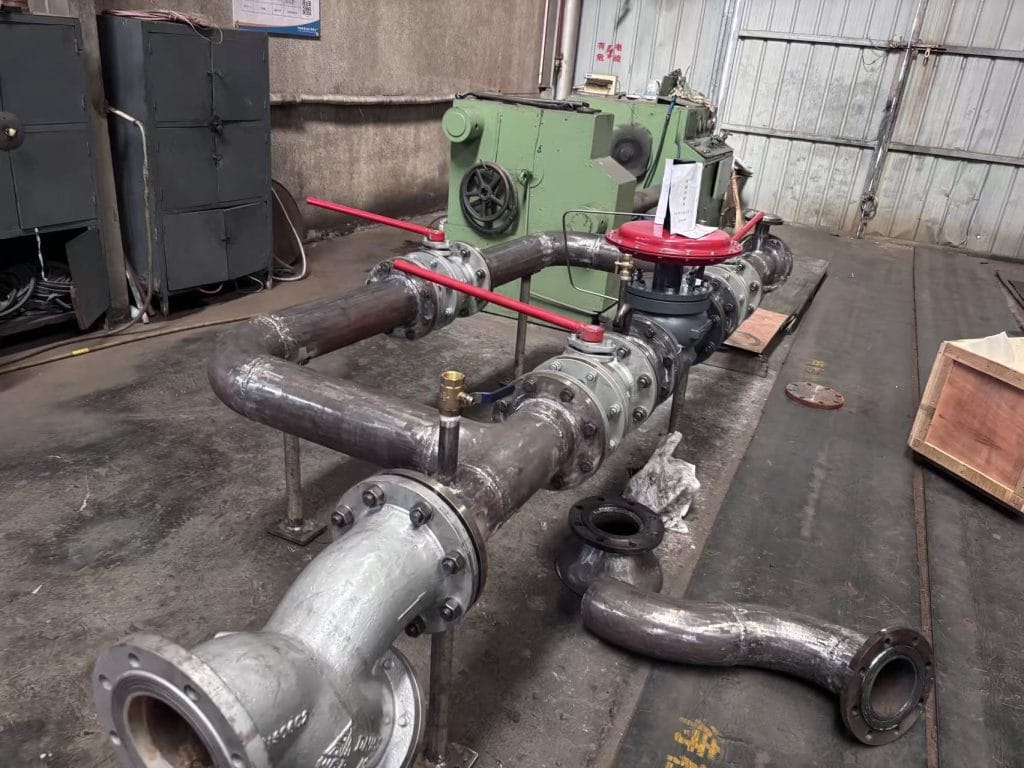
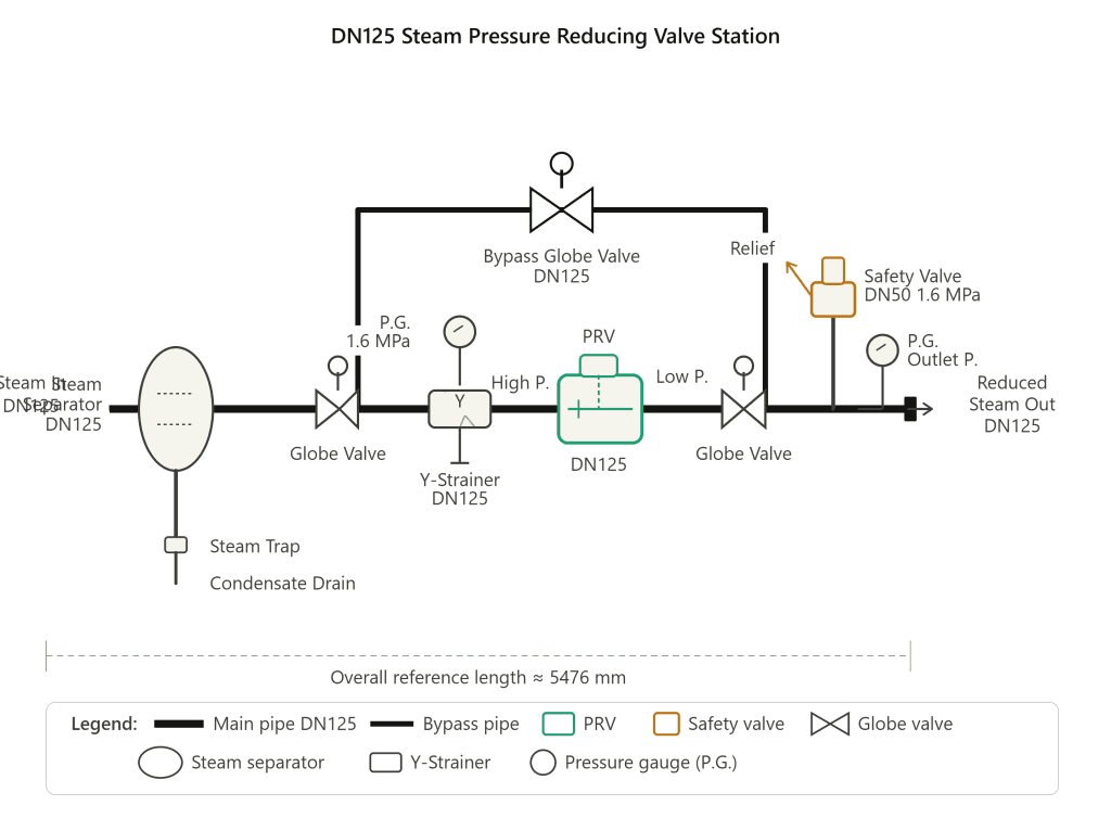
The DN125 Steam Pressure Reducing Valve Station (PRV Station) is a fully integrated skid assembly designed and manufactured to address exactly this challenge. Combining a steam separator, primary isolation valves, a Y-type strainer, a spring-loaded pressure reducing valve, a safety relief valve and instrumentation into one pre-engineered unit, the station eliminates the complexity and risk of field-assembled pressure management systems.
With a nominal pipe diameter of DN125 (5 inches) and a rated inlet pressure of up to 1.6 MPa (16 bar), this skid is sized for medium-to-large scale steam distribution applications across a broad range of industries.
Application Scenarios
The DN125 PRV Station is engineered for any environment where high-pressure steam must be reduced, conditioned and safely distributed to downstream equipment. Typical applications include:
- Power generation plants — reducing main steam header pressure to turbine auxiliary systems, feedwater heating and steam-seal systems.
- Petrochemical and refinery facilities — supplying process vessels, heat exchangers and reboilers with stable, low-pressure steam.
- Pharmaceutical and food processing — providing clean, dry steam at precise pressures for sterilisation autoclaves, CIP systems and jacketed reactors.
- District heating networks — stepping down high-pressure transmission steam to building-level heating systems.
- Pulp and paper mills — feeding dryer cans, digesters and evaporators with regulated steam at defined pressures.
- Textile and rubber manufacturing — supplying vulcanising presses and calenders with accurately controlled steam pressure.
- Central utility plants and hospital complexes — managing multiple pressure zones from a single boiler source.
Wherever a large differential exists between supply pressure and process requirement, this station provides the controlled transition.
Component Breakdown and Function
Every element within the skid has been selected and positioned to address a specific engineering requirement. The table below summarises each major component, its specification and its role within the assembly.
| Component | Specification | Function |
| Steam Separator | DN125, vertical shell | Removes entrained condensate and water droplets from incoming steam, protecting downstream components from water hammer and erosion. Wet steam entering the skid exits as dry, saturated steam. |
| Steam Trap | Thermodynamic / Float type | Continuously discharges condensate collected in the separator to drain without releasing live steam. Prevents condensate accumulation that would otherwise reduce heat-transfer efficiency and cause slug flow. |
| Upstream Globe Valve | DN125, rising-stem | Primary isolation valve on the high-pressure inlet side. Allows safe isolation of the entire PRV train for maintenance or emergency shutdown without interrupting the bypass line. |
| Y-Type Strainer | DN125, 40-mesh screen | Captures scale, pipe debris and particulate matter before it can reach the PRV seat. Maintains clean seating surfaces and extends valve service life. Fitted with a blowdown port for in-service cleaning. |
| Pressure Reducing Valve (PRV) | DN125, spring-loaded, self-acting | The core control element of the assembly. Senses downstream pressure via a sensing line and modulates the valve plug position to maintain a constant, adjustable outlet set-point regardless of fluctuations in inlet pressure or downstream flow demand. |
| Downstream Globe Valve | DN125, rising-stem | Outlet isolation valve on the low-pressure side. Enables the PRV to be isolated and serviced while the bypass valve maintains steam supply continuity. |
| Bypass Globe Valve | DN125, rising-stem, top-mounted | Manually operated bypass circuit. During PRV maintenance or replacement, this valve is opened to route steam directly around the PRV train, ensuring uninterrupted production. |
| Safety Relief Valve | DN50, spring-loaded, 1.6 MPa set | Final overpressure protection device on the low-pressure header. Opens automatically if downstream pressure rises above the rated set point, venting steam to a safe location and preventing catastrophic system failure. |
| Upstream Pressure Gauge | 0–1.6 MPa dial, glycerine-filled | Provides continuous visual indication of inlet (high-side) steam pressure, allowing operators to monitor boiler supply conditions. |
| Downstream Pressure Gauge | 0–1.0 MPa dial (or as specified) | Indicates the regulated outlet pressure in real time. Essential for confirming PRV set-point accuracy and detecting process demand changes. |
Engineering Challenges Addressed
Field-built pressure management systems frequently suffer from a range of operational problems. The DN125 PRV Station has been designed from the ground up to solve each of these:
1. Water Hammer and Wet Steam Erosion
High-velocity slugs of condensate in steam lines — commonly known as water hammer — can rupture pipework, damage valve internals and destroy instrumentation within seconds. The steam separator at the inlet eliminates entrained moisture before it can reach any sensitive components, while the steam trap removes accumulated condensate on a continuous basis.
2. Pressure Instability and Process Variability
Fluctuating boiler pressure or varying process loads can cause downstream pressure to oscillate, resulting in inconsistent product quality and process upsets. The self-acting PRV maintains a constant outlet pressure across a wide range of inlet pressures and flow rates, decoupling downstream processes from supply-side variability.
3. Foreign-Particle Damage to Control Valves
Pipe scale, weld spatter and corrosion products are pervasive in steam systems and are a primary cause of PRV seat leakage and premature valve failure. The Y-strainer positioned upstream of the PRV intercepts particles before they can score or wire-draw the valve plug and seat, substantially extending the service interval of the most expensive component in the assembly.
4. Overpressure Risk on Low-Pressure Headers
PRV failure in the open position, or an accidental valve misoperation, can expose low-pressure equipment to full boiler pressure — a potentially catastrophic event. The safety relief valve on the outlet header provides a certified, independent last line of defence, automatically limiting downstream pressure to its set-point regardless of upstream conditions.
5. Maintenance Downtime and Production Loss
In traditional in-line PRV installations, any maintenance activity requires a complete system shutdown. The factory-built bypass circuit incorporated into this skid allows the PRV to be isolated, serviced and returned to service without interrupting steam supply to the process, significantly reducing planned downtime.
6. Installation Cost and Quality Variability
Field-assembled valve trains are subject to errors in component selection, layout and pipe fabrication quality. Delivering the station as a factory-built, hydrostatically tested skid eliminates site fabrication risk, reduces installation time by up to 60% and ensures repeatable engineering quality across multiple project sites.
Operating Precautions and Maintenance Guidelines
Correct commissioning, operation and maintenance are essential for safe, long-term performance. All personnel involved in the installation or operation of this equipment must be qualified in steam system safety practices and must comply with applicable national standards (e.g. GB 50316, ASME B31.1/B31.3 or EN 13480 as applicable).
Pre-Commissioning Checks
- Verify that all inlet and outlet pipe connections are aligned to the skid flanges without imposing bending moments or thermal stress on the skid pipework.
- Confirm that pipe supports and anchor points comply with the piping isometric drawing and that thermal expansion loops are in place on connected pipework.
- Inspect the strainer basket and PRV internals for transit damage or debris accumulation before introducing steam.
- Confirm that the safety relief valve discharge pipe is routed to a safe vent location and is adequately supported and free-draining.
- Verify that all instrument connections (pressure gauge impulse lines) are purged and open before start-up.
Start-Up Procedure
- Open the steam trap bypass valve (if installed) and allow the separator and pipework to warm through slowly for a minimum of 15 minutes to prevent thermal shock and water hammer.
- With both main isolation valves closed, slowly crack open the upstream globe valve by no more than 10–15% of full travel. Allow pressure to equalise across the PRV.
- Gradually open the upstream globe valve to the full-open position over a period of not less than 2 minutes.
- Open the downstream globe valve and monitor the outlet pressure gauge to confirm the PRV is regulating at the pre-set outlet pressure.
- Check all flanged joints, valve gland packings and instrument connections for leakage and tighten as necessary.
- Once stable operation is confirmed, close the steam trap bypass (if applicable) and confirm trap operation.
Routine Operation
- Check pressure gauge readings at the start of each shift. Any deviation from the set-point pressure should be investigated promptly.
- Inspect the safety relief valve seat area regularly for evidence of simmering or weeping, which may indicate the downstream pressure is approaching the set-point.
- Blow down the Y-strainer at intervals specified in the maintenance schedule (typically every 1,000 operating hours or quarterly, whichever is sooner) to remove accumulated debris.
- Test the steam trap operation by using a trap tester, an infrared thermometer or acoustic testing to confirm condensate is being discharged without live steam loss.
PRV Bypass Operation
- Before opening the bypass globe valve, confirm that downstream systems are rated for the unregulated inlet pressure or that additional safeguards are in place.
- Open the bypass valve slowly and in small increments. Manual bypass operation provides no automatic pressure regulation; operators must monitor the downstream pressure gauge continuously throughout the bypass period.
- Maintain a dedicated operator at the bypass valve whenever it is in service.
Maintenance Intervals
- PRV seat and plug inspection: every 2 years or at the first sign of outlet pressure drift.
- Safety relief valve lift test and recertification: annually, in compliance with local pressure vessel and safety regulations.
- Globe valve gland packing replacement: as required on evidence of gland leakage, or at each major overhaul.
- Full skid hydrostatic pressure test: following any major repair or component replacement.
- All gaskets and sealing elements should be replaced at each valve overhaul; never re-use compressed gaskets.
Safety Warnings
| ⚠ WARNING: Never attempt to adjust the PRV set-spring compression or the safety relief valve set-pressure while the system is pressurised unless specifically authorised to do so under a hot-work or live-system procedure. Adjustments must only be carried out by qualified personnel. |
| ⚠ WARNING: Steam at 1.6 MPa has a saturation temperature in excess of 200 °C. All maintenance activities on pressurised or recently de-pressurised components require appropriate personal protective equipment (PPE) including steam-rated gloves, face protection and insulated tools. |
| ⚠ WARNING: Do not under any circumstances block or pipe the safety relief valve discharge to a closed system. The relief valve discharge must vent freely to atmosphere or to a designated safe vent header. |
Technical Specifications
| Parameter | Value |
| Nominal Pipe Diameter | DN125 (5″) |
| Design Inlet Pressure | Up to 1.6 MPa (16 bar g) |
| Outlet Pressure Range | 0.2 – 1.0 MPa (adjustable) |
| Design Temperature | Up to 220 °C (saturated steam) |
| Pressure Ratio (max) | 5 : 1 (inlet : outlet) |
| Safety Valve Set Pressure | 1.6 MPa |
| Safety Valve Size | DN50 |
| Connection Standard | GB/T 17241, PN16 / ANSI 150 (per order) |
| Overall Reference Length | ≈ 5,476 mm |
| Applicable Standard | GB 50316 / ASME B31.1 |
Customisation and Engineering Support
Standard skid configurations cover the most common process requirements; however, the station can be factory-configured to customer specifications including alternative pressure ratings, extended inlet configurations, pneumatic or electric PRV actuation, additional instrumentation (e.g. thermowells, flow meters, transmitters), trace heating provisions and hot-dip galvanised or epoxy-coated structural steelwork for corrosive environments.
Our engineering team is available to review process data sheets, P&IDs and site constraints to develop a skid specification precisely matched to the application. Factory acceptance testing (FAT) can be witnessed by the client or third-party inspectors prior to despatch.
For enquiries, technical datasheets or project-specific quotations, please contact our sales engineering team.