
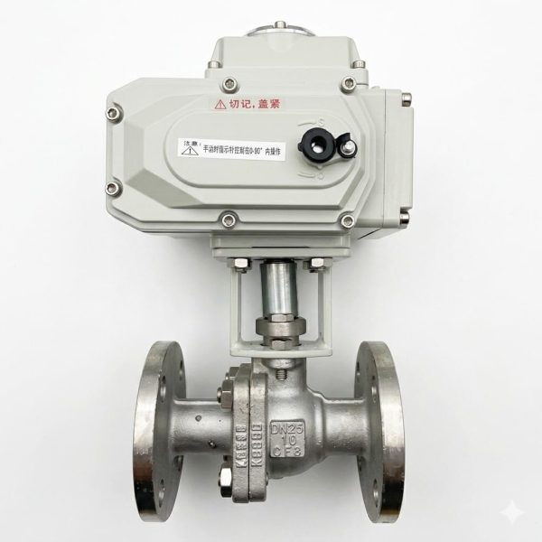
Q941F Motor Operated Ball Valve
• Motor operated ball valve with floating PTFE seat design
• 5 variants: Q941F-16Q/25Q/16C/25/40 covering PN16–PN40
• DN20–DN200, flanged ends, ≤200°C
• Actuator: On-Off / Modulating 4–20mA / Smart RS485 / Battery Backup
• QT450 ductile iron or WCB cast steel body with 2Cr13/304 trim
Gaoshan Valve — Q941F Motor Operated Ball Valve
Models: Q941F-16Q / Q941F-16C / Q941F-25Q / Q941F-25 / Q941F-40 | Pressure: PN16–PN40 | Connection: Flanged | DN Range: DN20–DN200 | Type: Electric Motor Actuated Floating Ball Valve
Steam
Oil Products
Petroleum
Non-Corrosive Fluids
Core Strengths
Product Overview
The Q941F series motor operated floating ball valve represents Gaoshan Valve’s solution for automated pipeline isolation requiring precise, electrically-driven shut-off capability in water, steam, oil, petroleum, and non-corrosive fluid services. Building upon the proven Q41F flanged ball valve platform, the Q941F integrates a compact electric motor actuator that converts electrical energy into precise quarter-turn rotary motion for full port opening and closing cycles. Available in five model variants covering three pressure classes (PN16, PN25, PN40) and two body material families (QT450 ductile iron for Q-suffix models, WCB cast steel for C models), the Q941F addresses applications ranging from municipal water distribution automation through heavy-duty industrial process control in refineries and chemical plants. The electric actuation approach offers distinct advantages over pneumatic alternatives including no compressed air infrastructure requirement, simpler electrical wiring, precise positioning with feedback, and quieter operation. Internal components including 2Cr13 or 304 stainless steel balls and stems, PTFE soft seat rings, anti-blowout stem designs, and bronze stem bearings are identical to the corresponding Q41F series valves, ensuring parts interchangeability and proven long-term reliability. Face-to-face dimensions comply with GB/T 12221 standards, flange connections follow GB/T 9113 / JB/T 79 specifications, and every valve undergoes rigorous testing per GB/T 13927 requirements.
Performance Specifications by Model
| Model | PN | Working Pressure (MPa) | Shell Test (MPa) | Seal Test (MPa) | Body Material | Max. Temp. |
| Q941F-16Q | 16 | 1.6 | 2.4 | 1.76 | Ductile Iron QT450 | ≤200°C |
| Q941F-16C | 16 | 1.6 | 2.4 | 1.76 | WCB Cast Steel | ≤200°C |
| Q941F-25Q | 25 | 2.5 | 3.75 | 2.75 | Ductile Iron QT450 | ≤200°C |
| Q941F-25 | 25 | 2.5 | 3.75 | 2.75 | WCB Cast Steel | ≤200°C |
| Q941F-40 | 40 | 4.0 | 6.0 | 4.4 | WCB Cast Steel | ≤200°C |
Materials of Main Parts
| Part Name | Material (Q Models) | Material (C Models) |
| Body & Bonnet | Ductile Cast Iron QT450-10 | Cast Carbon Steel WCB (ASTM A216) |
| Ball | Martensitic Stainless Steel 2Cr13 | Austenitic Stainless Steel 304 |
| Stem | Martensitic Stainless Steel 2Cr13 | Austenitic Stainless Steel 304 |
| Seat Ring | PTFE (Polytetrafluoroethylene) — Soft Seated | |
| Packing / Gasket | PTFE Packing + Flexible Graphite Gasket | |
| Actuator Housing | Die-Cast Aluminum Alloy with Powder-Coated Finish | |
| Motor | Induction Motor (AC) / Brushless DC Motor (DC option) | |
| Gear Train | Hardened Alloy Steel Worm / Worm Wheel with Grease Lubrication | |
| Position Indicator | Mechanical Pointer / LED Display (optional) | |
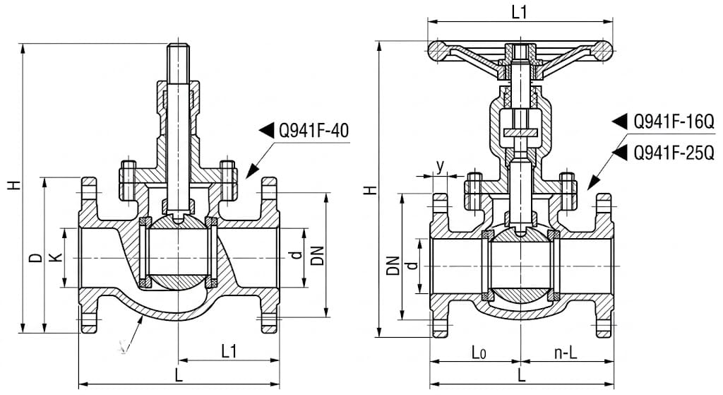
Main Dimensions — PN16 & PN25 Series (with Electric Actuator)
| DN | 20 | 25 | 32 | 40 | 50 | 65 | 80 | 100 | 125 | 150 | 200 |
| L (mm) | 140 | 160 | 165 | 180 | 200 | 220 | 250 | 280 | 320 | 360 | 457 |
| H (mm)* | 223 | 230 | 236 | 243 | 250 | 260 | 278 | 338 | 352 | 382 | 429 |
Main Dimensions — PN40 Series (with Electric Actuator)
| DN | 20 | 25 | 32 | 40 | 50 | 65 | 80 | 100 | 125 | 150 | 200 |
| L (mm) | 152 | 165 | 178 | 190 | 216 | 241 | 283 | 305 | 381 | 403 | 502 |
| H (mm)* | 223 | 230 | 236 | 243 | 250 | 260 | 278 | 338 | 352 | 382 | 429 |
* L = Face-to-Face Length, H = Overall Height (to top of electric actuator). Flange connection dimensions refer to GB/T 9113 Flange Dimension Table (Page P95). Technical specifications and main part materials are identical to corresponding Q41F-16Q, Q41F-16C, Q41F-25Q, Q41F-25, and Q41F-40 models.
Structure Drawing
Electric Actuator Options
- On-Off Type (Switching): Receives a simple open/close command signal (typically dry contact or 24V DC pulse) and drives the valve fully open or fully closed. Includes mechanical end-stop switches that cut power at the travel limits. Torque switches provide overload protection by stopping the motor if excessive resistance is encountered. The most economical configuration for basic isolation applications.
- Modulating Type (Proportional Control): Accepts a continuous 4–20 mA analog control signal and positions the ball proportionally between 0% and 100% open. The built-in positioner compares the input signal against actual valve position from the potentiometer or encoder feedback, continuously adjusting motor drive to minimize deviation. Response time and deadband are factory-calibrated for smooth process control in throttling applications.
- Smart Type (Digital Communication): Equipped with an intelligent control module supporting Modbus RTU/RS485, Profibus DP, or HART protocol for direct digital integration into plant DCS systems. Provides diagnostic data including valve position, torque profile, cycle count, temperature, and fault history. Remote parameter adjustment, partial stroke testing (PST), and emergency shutdown (ESD) functions are configurable via software.
- Fail-Safe Battery Backup: Optional built-in battery pack enables the actuator to complete one full open or close cycle upon main power failure. The battery maintains charge via the main supply and switches automatically when voltage drops below threshold. Ideal for critical applications requiring guaranteed valve positioning during power outages without the complexity of pneumatic spring-return systems.
Design & Manufacturing Standards
- Design Standard: GB/T 12237 (Flanged Ball Valves)
- Face-to-Face Dimensions: GB/T 12221
- Flange Standards: GB/T 9113 (RF), JB/T 79 (for PN40)
- Testing & Inspection: GB/T 13927
- Ductile Iron Material: QT450-10 per GB/T 1348
- Cast Steel Material: WCB per ASTM A216 / JB/T 9626
- Actuator Mounting Interface: ISO 5211
- Motor Protection Rating: IP67 (standard), IP68 (optional)
- Applicable International Standards: API 608, BS 5351, IEC 60534 (actuator)
Installation & Commissioning Guidelines
- Pipeline Preparation: Clean all pipe ends thoroughly before installation, removing welding slag, scale, rust, and foreign debris. Flush the complete pipeline system to eliminate particles that could damage PTFE seats during first operation. Use gaskets rated for the specific pressure class (PN16/25/40) and temperature rating of the application.
- Installation Clearance: Ensure adequate overhead clearance above the valve for the electric actuator height (refer to H dimension table — ranging from 223mm for DN20 to 429mm for DN200). Also allow lateral clearance for actuator wiring conduit access, manual override handwheel operation, and removal of the actuator cover for maintenance. For outdoor installations, ensure the actuator housing is protected from direct rain exposure or specify an IP68-rated weatherproof enclosure.
- Flange Alignment & Bolt Tightening: Align the valve flanges concentrically with mating pipe flanges before inserting bolts. Tighten flange bolts in a cross-star pattern in multiple incremental passes to achieve uniform gasket compression. Never fully tighten one side first — uneven bolt loading causes body distortion that binds the floating ball against the seats, increasing breakaway torque and causing premature seat wear.
- Electrical Connections: Wire the actuator according to the terminal diagram provided with the unit, ensuring proper grounding per local electrical codes. Use appropriately sized cable glands rated for the conduit diameter and environmental conditions. For 380V three-phase installations, verify correct phase sequence — reversing two phases will cause the motor to run in the opposite direction. Install an appropriately rated circuit breaker or fused disconnect within sight of the valve.
- Commissioning Procedure: Before energizing the actuator, manually verify the valve moves freely through its full travel using the manual override handwheel. Apply power and perform a full open-close-open cycle at reduced load (system depressurized if possible). Verify correct rotation direction, end-stop switch function, and torque switch calibration. Check limit switch signal feedback at the control panel to confirm remote position indication accuracy.
- Modulating Actuator Calibration: If equipped with a 4–20 mA positioner, connect a calibrated signal source and verify zero point (4 mA = fully closed) and span (20 mA = fully open) alignment within ±1% of travel. Adjust gain and damping parameters to achieve stable positioning without oscillation under actual process load conditions. Record the calibrated position vs. signal table for operator reference.
- Emergency Operation Verification: Test the manual override handwheel to confirm it disengages the motor clutch smoothly and allows full manual operation with reasonable effort. If equipped with battery backup fail-safe, simulate a power failure and verify the valve completes its programmed safe position movement within the specified time. Document the actual fail-safe response time for plant safety records.
- Preventive Maintenance Schedule: Inspect actuator housing seals and cable glands every 12 months for degradation or water ingress. Check and retighten terminal block connections annually to prevent loosening from thermal cycling. Lubricate the manual override clutch mechanism and handwheel bearing annually with lithium-based grease. Verify torque switch calibration every 24 months using a calibrated torque measurement device.
Application Fields
Wastewater Treatment Plants
Oil Refineries & Petrochemical Plants
Power Plant Auxiliary Systems
HVAC Central Plant Control
Chemical Process Automation
Tank Farm Automated Isolation
Building Management Systems (BMS)
Food & Beverage Processing
Irrigation & Agricultural Systems
Get a Quote & Technical Support
Contact Gaoshan Valve today for detailed dimension sheets, CAD drawings, actuator specification sheets, wiring diagrams, material certificates, and customized Q941F motor operated ball valve solutions for your automated process control requirements.